Engine Hybrid System. Corolla. Zre142 Aze141
2Zr-Fe Engine Control. Corolla. Zre142 Aze141
TYPICAL MALFUNCTION THRESHOLDS
CHECK ANY OTHER DTCS OUTPUT (IN ADDITION TO DTC P0101)
DTC P0101 Mass Air Flow Circuit Range / Performance Problem |
DESCRIPTION
Refer to DTC P0102 (Link).| DTC No. | DTC Detection Condition | Trouble Area |
| P0101 | Conditions (a), (b), (c), (d) and (e) continue for 10 seconds (2 trip detection logic): (a) Engine running (b) Engine coolant temperature 70°C (158°F) or more (c) Throttle position sensor voltage 0.2 V or more, and less than 2 V (d) Average engine load value ratio less than 0.85, or more than 1.23 (varies with estimated engine load) Average engine load value ratio = Average engine load based on mass air flow meter output / Average engine load estimated from driving conditions (e) Average air fuel ratio less than -20%, or more than 20% |
|
MONITOR DESCRIPTION
The mass air flow meter is a sensor that measures the amount of air flowing through the throttle valve. The ECM uses this information to determine the fuel injection time and to provide an appropriate air fuel ratio. Inside the mass air flow meter, there is a heated platinum wire which is exposed to the flow of intake air. By applying a specific electrical current to the wire, the ECM heats it to a specific temperature. The flow of incoming air cools both the wire and an internal thermistor, affecting their resistance. To maintain a constant current value, the ECM varies the voltage applied to the mass air flow meter. The voltage level is proportional to the air flow through the sensor, and the ECM uses it to calculate the intake air volume.The ECM monitors the average engine load value ratio to check the mass air flow meter for malfunctions. The average engine load value ratio is obtained by comparing the average engine load calculated from the mass air flow meter output to the average engine load estimated from the driving conditions, such as the engine speed and the throttle opening angle. If the average engine load value ratio is below the threshold value, the ECM determines that the intake air volume is low, and if the average engine load value ratio is above the threshold value, the ECM determines that the intake air volume is high.
If this is detected in 2 consecutive driving cycles, the MIL is illuminated and the DTC is set.
MONITOR STRATEGY
| Related DTCs | P0101: Mass air flow meter rationality |
| Required Sensors/Components (Main) | Mass air flow meter |
| Required Sensors/Components (Related) | Crankshaft position sensor Camshaft position sensor Engine coolant temperature sensor Throttle position sensor |
| Frequency of Operation | Continuous |
| Duration | 10 times |
| MIL Operation | 2 driving cycles |
| Sequence of Operation | None |
TYPICAL ENABLING CONDITIONS
| Monitor runs whenever following DTCs not present | None |
| (Throttle position sensor voltage - (learned throttle position sensor closed position voltage + ISC voltage)) | 0.2 V or more, and less than 2 V |
| Time after engine starts | 5 seconds or more |
| Battery voltage | 10.5 V or more |
| Engine coolant temperature | 70°C (158°F) or more |
| Estimated Load | 30% or more, and less than 70% |
| Mass air flow meter circuit fail (P0102, P0103) | Not detected |
| Intake air temperature sensor circuit fail (P0112, P0113) | Not detected |
| Engine coolant temperature sensor circuit fail (P0115, P0117, P0118) | Not detected |
| Crankshaft position sensor circuit fail (P0335) | Not detected |
| Throttle position sensor circuit fail (P0120, P0121, P0122, P0123, P0220, P0222, P0223, P2135) | Not detected |
| Canister pressure sensor circuit fail (P0452, P0453) | Not detected |
| Leak detection pump fail (P2401, P2402) | Not detected |
| Vent valve fail (P2419, P2420) | Not detected |
TYPICAL MALFUNCTION THRESHOLDS
| Both of following conditions 1 and 2 met | - |
| 1. Averaged engine load value ratio | Less than 0.85, or more than 1.23 (varies with estimated engine load) |
| 2. Averaged air fuel ratio | Less than -20%, or more than 20% |
CONFIRMATION DRIVING PATTERN
- Connect the Techstream to the DLC3.
- Turn the ignition switch to ON.
- Turn the Techstream on.
- Clear the DTCs (even if no DTCs are stored, perform the clear DTC operation) (COROLLA_ZRE142 RM000000PDK0ZAX.html).
- Turn the ignition switch off and wait for at least 30 seconds.
- Turn the ignition switch to ON and turn the Techstream on.
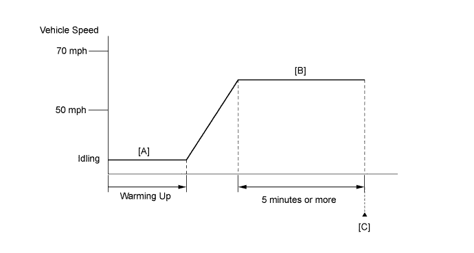
- Start the engine and warm it up until the engine coolant temperature reaches 70°C (158°F) or higher [A].
- Drive the vehicle at approximately 50 mph (80 km/h) to 70 mph (112 km/h) for 5 minutes or more [B].
- CAUTION:
- When performing the confirmation driving pattern, obey all speed limits and traffic laws.
- HINT:
- Drive while keeping the engine load as stable as possible.
- Enter the following menus: Powertrain / Engine and ECT / Trouble Codes [C].
- Read the pending DTCs.
- HINT:
- If a pending DTC is output, the system is malfunctioning.
- If a pending DTC is not output, perform the following procedure.
- Enter the following menus: Powertrain / Engine and ECT / Utility / All Readiness.
- Input the DTC: P0101.
- Check the DTC judgment result.
Techstream Display Description NORMAL - DTC judgment completed
- System normal
ABNORMAL - DTC judgment completed
- System abnormal
INCOMPLETE - DTC judgment not completed
- Perform driving pattern after confirming DTC enabling conditions
N/A - Unable to perform DTC judgment
- Number of DTCs which do not fulfill DTC preconditions has reached ECU memory limit
- HINT:
- If the judgment result shows NORMAL, the system is normal.
- If the judgment result shows ABNORMAL, the system has a malfunction.
- If the judgment result shows INCOMPLETE or N/A, perform steps [B] and [C] again.
- DTC judgment completed
- If no pending DTC is output, perform a universal trip and check for permanent DTCs (COROLLA_ZRE142 RM000000PDK0ZAX.html).
- HINT:
- If a permanent DTC is output, the system is malfunctioning.
- If no permanent DTC is output, the system is normal.
WIRING DIAGRAM
Refer to DTC P0102 (COROLLA_ZRE142 RM000000U5B0NJX_07.html).INSPECTION PROCEDURE
- HINT:
- Read freeze frame data using the Techstream. The ECM records vehicle and driving condition information as freeze frame data the moment a DTC is stored. When troubleshooting, freeze frame data can be helpful in determining whether the vehicle was running or stopped, whether the engine was warmed up or not, whether the air fuel ratio was lean or rich, as well as other data recorded at the time of a malfunction.
| 1.CHECK ANY OTHER DTCS OUTPUT (IN ADDITION TO DTC P0101) |
Connect the Techstream to the DLC3.
Turn the ignition switch to ON.
Turn the Techstream on.
Enter the following menus: Powertrain / Engine and ECT / Trouble Codes.
Read the DTCs.
- Result:
Result Proceed to DTC P0101 is output A DTC P0101 and other DTCs are output B
- HINT:
- If any DTCs other than P0101 are output, troubleshoot those DTCs first.
|
| ||||
| A | |
| 2.CHECK INTAKE SYSTEM |
Check the intake system for vacuum leaks (COROLLA_ZRE142 RM000003410016X.html).
- OK:
- No leaks from intake system.
|
| ||||
| OK | |
| 3.CHECK PCV HOSE CONNECTIONS |
Check the PCV hose connections (COROLLA_ZRE142 RM0000012OO05EX_01_0003.html).
- OK:
- PCV hose is connected correctly and is not damaged.
|
| ||||
| OK | ||
| ||