Communication System. Camry. Acv40 Gsv40
Can Communication. Camry. Acv40 Gsv40
CHECK FOR OPEN IN ONE SIDE OF CAN BRANCH WIRE
CAN COMMUNICATION SYSTEM (for RHD) - Open in One Side of CAN Branch Line |
DESCRIPTION
If 2 or more ECUs and/or sensors do not appear on the intelligent tester "Communication Bus Check" screen, one side of the CAN branch wire may be open. (One side of the CAN-H [branch wire] / CAN-L [branch wire] of the ECU and/or sensor is open.)| Symptom | Trouble Area |
| 2 or more ECUs and/or sensors do not appear on the intelligent tester "Communication Bus Check" screen. |
|
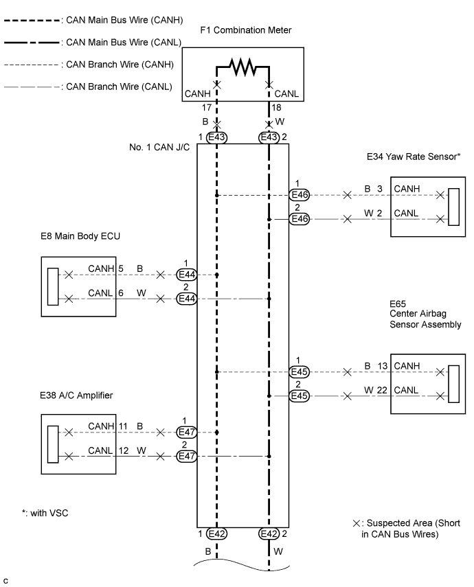
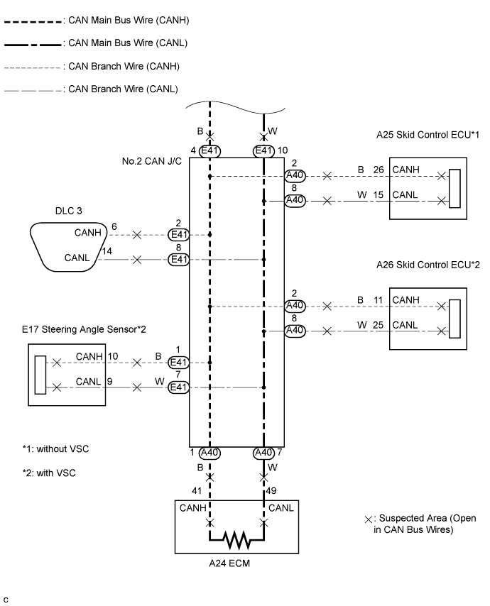
WIRING DIAGRAM
INSPECTION PROCEDURE
- NOTICE:
- Turn the ignition switch off before measuring the resistance of the CAN main wire and CAN branch wires.
- After the ignition switch is turned off, check that the key reminder warning system and lighting system are not operating.
- Before measuring the resistance, leave the vehicle as is for at least 1 minute and do not operate the ignition switch, any other switches or the doors. If doors need to be opened in order to check connectors, open the doors and leave them open.
- HINT:
- Operating the ignition switch, any other switches or any triggers related ECU and sensor communication on the CAN, which would cause resistance reading variations.
| 1.CHECK FOR OPEN IN ONE SIDE OF CAN BRANCH WIRE |
Confirm the systems (ECUs and sensors), which use CAN communication, equipped on the vehicle. (CAMRY_ACV40 RM000000WIB09KX.html)
Using the intelligent tester, select and perform "Communication Bus Check". (CAMRY_ACV40 RM000000WIB09KX.html) [*1]
Disconnect the connectors from the ECUs or sensors that are not displayed on the screen. [*2]
Check that only the ECUs and sensors from which the connectors were disconnected in the previous step are not displayed on the "Communication Bus Check" screen. [*3]
- HINT:
- If any ECUs or sensors, other than those from which the connectors were disconnected in the previous step, are not displayed on the "Communication Bus Check" screen, reconnect the disconnected connectors and repeat the procedures [*1], [*2], and [*3].
Perform the communication stop mode check for the ECUs and sensors which correspond to the disconnected connectors. (CAMRY_ACV40 RM000000WI808ZX.html)
| NEXT | ||
| ||