Can Communication System (For Rhd) Open In Can Main Bus Line
DESCRIPTION
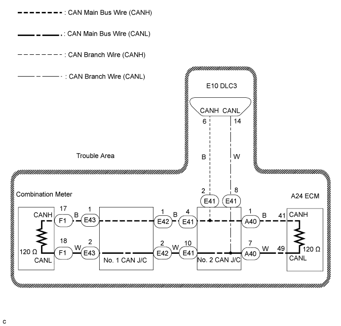
WIRING DIAGRAM
INSPECTION PROCEDURE
CHECK DLC3
CHECK FOR OPEN IN CAN BUS MAIN WIRE (COMBINATION METER MAIN BUS WIRE)
CHECK FOR OPEN IN CAN BUS MAIN WIRE (NO. 1 CAN J/C)
CHECK FOR OPEN IN CAN BUS MAIN WIRE (NO. 2 CAN J/C - ECM)
CHECK FOR OPEN IN CAN BUS MAIN WIRE (ECM CAN MAIN BUS WIRE)
CHECK FOR OPEN IN CAN BUS MAIN WIRE (COMBINATION METER - NO. 1 CAN J/C)
CHECK FOR OPEN IN CAN BUS MAIN WIRE (NO. 1 CAN J/C - NO. 2 CAN J/C)
CAN COMMUNICATION SYSTEM (for RHD) - Open in CAN Main Bus Line |
DESCRIPTION
There may be an open circuit in the CAN main bus wire and/or the DLC3 branch wire when the resistance between terminals 6 (CANH) and 14 (CANL) of the DLC3 is 70Ω or more.Symptom
| Trouble Area
|
Resistance between terminals 6 (CANH) and 14 (CANL) of the DLC3 is 70 Ω or more.
| - CAN main bus wire or connector
- No. 1 CAN J/C
- No. 2 CAN J/C
- DLC3 branch wire or connector
- Combination meter
- ECM
|
WIRING DIAGRAM
INSPECTION PROCEDURE
- NOTICE:
- Turn the ignition switch off before measuring the resistance of the CAN main wire and CAN branch wires.
- After the ignition switch is turned off, check that the key reminder warning system and lighting system are not operating.
- Before measuring the resistance, leave the vehicle as is for at least 1 minute and do not operate the ignition switch, any other switches or the doors. If doors need to be opened in order to check connectors, open the doors and leave them open.
- HINT:
- Operating the ignition switch, any other switches or any triggers related ECU and sensor communication on the CAN, which would cause resistance reading variations.
Turn the ignition switch off.
Measure the resistance according to the value(s) in the table below.
- Standard resistance:
Tester Connection
| Condition
| Specified Value
| Result
|
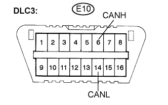
E10-6 (CANH) -E10-14 (CANL)
| Ignition switch off
| 108 to 132 Ω
| A
|
E10-6 (CANH) - E10-14 (CANL)
| Ignition switch off
| 133 Ω or higher
| B
|
- NOTICE:
- When the measured value is 133 Ω or more and a CAN communication system diagnostic trouble code is output, there may be a fault besides disconnection of the DLC3 branch wire. For that reason, troubleshooting should be performed again from "HOW TO PROCEED WITH TROUBLESHOOTING" (CAMRY_ACV40 RM000000WI605KX.html ) after repairing the trouble area.
| | REPAIR OR REPLACE DLC3 BRANCH WIRE OR CONNECTOR (CANH, CANL) |
|
|
| 2.CHECK FOR OPEN IN CAN BUS MAIN WIRE (COMBINATION METER MAIN BUS WIRE) |
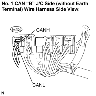
Disconnect the CAN main bus wire connector (E43) from the No. 1 CAN J/C "B" side (without earth terminal).
- NOTICE:
- Before disconnecting the connector, make a note of where it is connected.
- Reconnect the connector to its original position.
Measure the resistance according to the value(s) in the table below.
- Standard resistance:
Tester Connection
| Condition
| Specified Value
|
E43-1 (CANH) - E43-2 (CANL)
| Ignition switch off
| 108 to 132 Ω
|
| 3.CHECK FOR OPEN IN CAN BUS MAIN WIRE (NO. 1 CAN J/C) |
Reconnect the CAN main bus wire connector (E43) to the No. 1 CAN J/C "B" side (without earth terminal).
Disconnect the CAN main bus wire connector (E42) from the No. 1 CAN J/C "A" side (with earth terminal).
- NOTICE:
- Before disconnecting the connector, make a note of where it is connected.
- Reconnect the connector to its original position.
Measure the resistance according to the value(s) in the table below.
- Standard resistance:
Tester Connection
| Condition
| Specified Value
|
E42-1 (CANH) - E42-2 (CANL)
| Ignition switch off
| 108 to 132 Ω
|
| 4.CHECK FOR OPEN IN CAN BUS MAIN WIRE (NO. 2 CAN J/C - ECM) |
Reconnect the CAN main bus wire connector (E42) to the No. 1 CAN J/C (with earth terminal).
Disconnect the CAN main bus wire connector (A40) from the No. 2 CAN J/C (rear of the vehicle).
Measure the resistance according to the value(s) in the table below.
- Standard resistance:
Tester Connection
| Condition
| Specified Value
|
A40-1 (CANH) - A40-7 (CANL)
| Ignition switch off
| 108 to 132 Ω
|
| 5.CHECK FOR OPEN IN CAN BUS MAIN WIRE (ECM CAN MAIN BUS WIRE) |
Reconnect the CAN main bus wire connector (A40) to the No. 2 CAN J/C (rear of the vehicle).
Disconnect the A24 ECM connector.
Measure the resistance according to the value(s) in the table below.
- Standard resistance:
Tester Connection
| Condition
| Specified Value
|
A24-41 (CANH) - A24-49 (CANL)
| Ignition switch off
| 108 to 132 Ω
|
| NG |
|
|
|
| REPAIR OR REPLACE CAN BUS MAIN WIRE OR CONNECTOR (NO. 2 CAN J/C - ECM) |
|
| 6.CHECK FOR OPEN IN CAN BUS MAIN WIRE (COMBINATION METER - NO. 1 CAN J/C) |
Reconnect the CAN main bus wire connector (E43) to the No. 1 CAN J/C "B" side (without earth terminal).
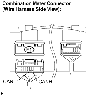
Disconnect the combination meter connector (F1).
Measure the resistance according to the value(s) in the table below.
- Standard resistance:
Tester Connection
| Condition
| Specified Value
|
F1-17 (CANH) - F1-18 (CANL)
| Ignition switch off
| 108 to 132 Ω
|
| | REPLACE COMBINATION METER |
|
|
| NG |
|
|
|
| REPAIR OR REPLACE CAN BUS MAIN WIRE OR CONNECTOR (NO. 1 CAN J/C - COMBINATION METER) |
|
| 7.CHECK FOR OPEN IN CAN BUS MAIN WIRE (NO. 1 CAN J/C - NO. 2 CAN J/C) |
Reconnect the CAN main bus wire connector (A40) to the No. 2 CAN J/C (rear of the vehicle).
Disconnect the CAN main bus wire connector (E41) from the No. 2 CAN J/C (front of the vehicle).
Measure the resistance according to the value(s) in the table below.
- Standard resistance:
Tester Connection
| Specified Value
|
E41-4 (CANH) - E41-10 (CANL)
| 108 to 132 Ω
|
| | REPAIR OR REPLACE CAN BUS MAIN WIRE OR CONNECTOR (NO. 1 CAN J/C - NO. 2 CAN J/C) |
|
|