DESCRIPTION
WIRING DIAGRAM
INSPECTION PROCEDURE
SYSTEM CHECK
CHECK HARNESS AND CONNECTOR (MAIN BODY ECU - EACH ECU)
CHECK DTC OUTPUT (POWER WINDOW REGULATOR MOTOR ASSEMBLY (for DRIVER SIDE))
CHECK DTC OUTPUT (POWER WINDOW REGULATOR MOTOR ASSEMBLY (for FRONT PASSENGER SIDE))
CHECK DTC OUTPUT (POWER WINDOW REGULATOR MOTOR ASSEMBLY (for REAR RH SIDE))
CHECK DTC OUTPUT (POWER WINDOW REGULATOR MOTOR ASSEMBLY (for REAR LH SIDE))
CHECK DTC OUTPUT (POWER WINDOW REGULATOR MASTER SWITCH ASSEMBLY)
CHECK DTC OUTPUT (SLIDING ROOF ECU (SLIDING ROOF DRIVE GEAR SUB-ASSEMBLY))
CHECK HARNESS AND CONNECTOR (MAIN BODY ECU - EACH ECU)
CHECK DTC OUTPUT (POWER WINDOW REGULATOR MOTOR ASSEMBLY (FOR DRIVER SIDE))
CHECK DTC OUTPUT (SLIDING ROOF ECU (SLIDING ROOF DRIVE GEAR SUB-ASSEMBLY))
DTC B2325 LIN Communication Bus Malfunction |
DESCRIPTION
The main body ECU (instrument panel junction block) monitors communication between all the ECUs connected to the door bus lines. When the main body ECU (instrument panel junction block) detects errors in communication with all the ECUs connected to the door bus lines at 2.6-second intervals and 3 times in a row, DTC B2325 will be stored.DTC Code
| DTC Detection Condition
| Trouble Area
|
B2325
| Main body ECU (instrument panel junction block) detects errors in communication with the ECUs connected to the door bus lines 3 times in a row.
| - Power window regulator master switch assembly*1
- Sliding roof ECU (Sliding roof drive gear sub-assembly)*2
- Power window regulator motor assembly (for Driver side)
- Power window regulator motor assembly (for Front passenger side)*1
- Power window regulator motor assembly (for Rear RH side)*1
- Power window regulator motor assembly (for Rear LH side)*1
- Main body ECU (Instrument panel junction block)
- Wire harness or connector
|
- *1: for LHD
- *2: w/ Sliding Roof System
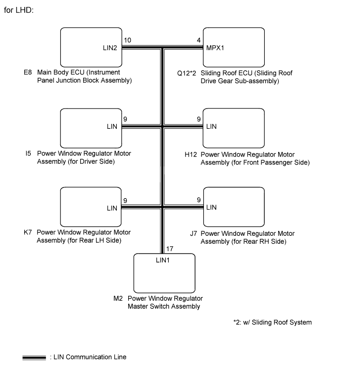
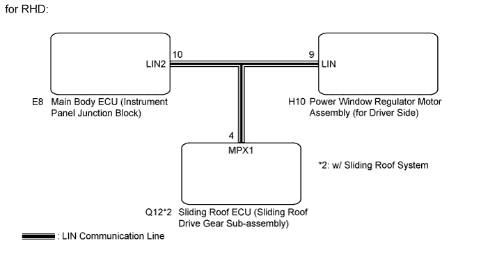
WIRING DIAGRAM
INSPECTION PROCEDURE
- NOTICE:
- When the sliding roof ECU (sliding roof drive gear sub-assembly) is replaced or removed and reinstalled, it requires initialization (CAMRY_ACV40 RM000001VJR004X.html).
- When a power window regulator motor assembly is replaced or removed and reinstalled, it requires initialization (CAMRY_ACV40 RM0000011V202ZX.html for LHD, CAMRY_ACV40 RM0000011V200KX.html for RHD).
- When using the intelligent tester to troubleshoot with the ignition switch off:
Connect the intelligent tester to the DLC3, and turn the courtesy switch on and off at 1.5-second intervals until communication between the intelligent tester and vehicle begins.
Check the vehicle specification.
- Result:
Result
| Proceed to
|
for LHD
| A
|
for RHD
| B
|
| 2.CHECK HARNESS AND CONNECTOR (MAIN BODY ECU - EACH ECU) |
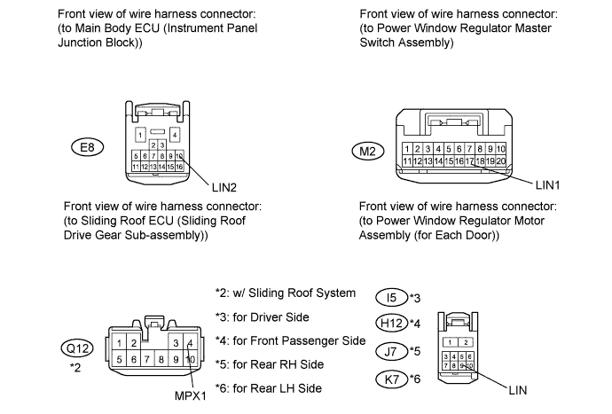
Disconnect the E8 and Q12*2 ECU connectors.
- *2: w/ Sliding Roof System
Disconnect the I5, H12, J7 and K7 motor connectors.
Disconnect the M2 switch connector.
Measure the resistance and voltage according to the value(s) in the table below.
- Standard resistance:
Tester Connection
| Condition
| Specified Condition
|
E8-10 (LIN2) - M2-17 (LIN1)
| Always
| Below 1 Ω
|
E8-10 (LIN2) - I5-9 (LIN)
| Always
| Below 1 Ω
|
E8-10 (LIN2) - H12-9 (LIN)
| Always
| Below 1 Ω
|
E8-10 (LIN2) - J7-9 (LIN)
| Always
| Below 1 Ω
|
E8-10 (LIN2) - K7-9 (LIN)
| Always
| Below 1 Ω
|
E8-10 (LIN2) - Q12-4 (MPX1)*2
| Always
| Below 1 Ω
|
E8-10 (LIN2) - Body ground
| Always
| 10 kΩ or higher
|
- Standard voltage:
Tester Connection
| Condition
| Specified Condition
|
E8-10 (LIN2) - Body ground
| Always
| Below 1 V
|
- *2: w/ Sliding Roof System
| | REPAIR OR REPLACE HARNESS OR CONNECTOR |
|
|
| 3.CHECK DTC OUTPUT (POWER WINDOW REGULATOR MOTOR ASSEMBLY (for DRIVER SIDE)) |
Reconnect the E8 and Q12*2 ECU connectors.
- *2: w/ Sliding Roof System
Reconnect the H12, J7 and K7 motor connectors.
Reconnect the M2 switch connector.
Clear the DTC (CAMRY_ACV40 RM000002XHS00KX.html).
Recheck for DTCs.
- Result:
Result
| Proceed to
|
DTC B2325 is output
| A
|
DTC B2325 is not output
| B
|
| 4.CHECK DTC OUTPUT (POWER WINDOW REGULATOR MOTOR ASSEMBLY (for FRONT PASSENGER SIDE)) |
Reconnect the I5 motor connector.
Disconnect the H12 motor connector.
Clear the DTC (CAMRY_ACV40 RM000002XHS00KX.html).
Recheck for DTCs.
- Result:
Result
| Proceed to
|
DTC B2325 is output
| A
|
DTC B2325 is not output
| B
|
| 5.CHECK DTC OUTPUT (POWER WINDOW REGULATOR MOTOR ASSEMBLY (for REAR RH SIDE)) |
Reconnect the H12 motor connector.
Disconnect the J7 motor connector.
Clear the DTC (CAMRY_ACV40 RM000002XHS00KX.html).
Recheck for DTCs.
- Result:
Result
| Proceed to
|
DTC B2325 is output
| A
|
DTC B2325 is not output
| B
|
| 6.CHECK DTC OUTPUT (POWER WINDOW REGULATOR MOTOR ASSEMBLY (for REAR LH SIDE)) |
Reconnect the J7 motor connector.
Disconnect the K7 motor connector.
Clear the DTC (CAMRY_ACV40 RM000002XHS00KX.html).
Recheck for DTCs.
- Result:
Result
| Proceed to
|
DTC B2325 is output
| A
|
DTC B2325 is not output
| B
|
| 7.CHECK DTC OUTPUT (POWER WINDOW REGULATOR MASTER SWITCH ASSEMBLY) |
Reconnect the K7 motor connector.
Disconnect the M2 switch connector.
Clear the DTC (CAMRY_ACV40 RM000002XHS00KX.html).
Recheck for DTCs.
- Result:
Result
| Proceed to
|
DTC B2325 is output (w/ Sliding Roof System)
| A
|
DTC B2325 is output (w/o Sliding Roof System)
| B
|
DTC B2325 is not output
| C
|
| | REPLACE MAIN BODY ECU (INSTRUMENT PANEL JUNCTION BLOCK) |
|
|
| |
|
| 8.CHECK DTC OUTPUT (SLIDING ROOF ECU (SLIDING ROOF DRIVE GEAR SUB-ASSEMBLY)) |
Reconnect the M2 switch connector.
Disconnect the Q12 ECU connector.
Clear the DTC (CAMRY_ACV40 RM000002XHS00KX.html).
Recheck for DTCs.
- Result:
Result
| Proceed to
|
DTC B2325 is output
| A
|
DTC B2325 is not output
| B
|
| A |
|
|
|
| REPLACE MAIN BODY ECU (INSTRUMENT PANEL JUNCTION BLOCK) |
|
| 9.CHECK HARNESS AND CONNECTOR (MAIN BODY ECU - EACH ECU) |
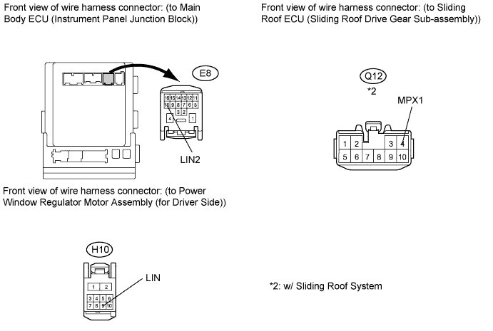
Disconnect the E8 and H10 connectors.
Disconnect the Q12*2 connector.
- *2: w/ Sliding Roof System
Measure the resistance and voltage according to the value(s) in the table below.
- Standard resistance:
Tester Connection
| Condition
| Specified Condition
|
E8-10 (LIN2) - H10-9 (LIN)
| Always
| Below 1 Ω
|
E8-10 (LIN2) - Q12-4 (MPX1)*2
| Always
| Below 1 Ω
|
E8-10 (LIN2) - Body ground
| Always
| 10 kΩ or higher
|
- Standard voltage:
Tester Connection
| Condition
| Specified Condition
|
E8-10 (LIN2) - Body ground
| Always
| Below 1 V
|
- *2: w/ Sliding Roof System
| | REPAIR OR REPLACE HARNESS OR CONNECTOR |
|
|
| 10.CHECK DTC OUTPUT (POWER WINDOW REGULATOR MOTOR ASSEMBLY (FOR DRIVER SIDE)) |
Reconnect the E8 and Q12*2 connectors.
- *2: w/ Sliding Roof System
Clear the DTC (CAMRY_ACV40 RM000002XHS00KX.html).
Recheck for DTCs.
- Result:
Result
| Proceed to
|
B2325 is output (w/ Sliding Roof System)
| A
|
B2325 is output (w/o Sliding Roof System)
| B
|
B2325 is not output
| C
|
| | REPLACE MAIN BODY ECU (INSTRUMENT PANEL JUNCTION BLOCK) |
|
|
| |
|
| 11.CHECK DTC OUTPUT (SLIDING ROOF ECU (SLIDING ROOF DRIVE GEAR SUB-ASSEMBLY)) |
Reconnect the H10 connector.
Disconnect the Q12 connector.
Clear the DTC (CAMRY_ACV40 RM000002XHS00KX.html).
Recheck for DTCs.
- Result:
Result
| Proceed to
|
B2325 is output
| A
|
B2325 is not output
| B
|
| A |
|
|
|
| REPLACE MAIN BODY ECU (INSTRUMENT PANEL JUNCTION BLOCK) |
|