Toyota Parking Assist-Sensor System Front Clearance Sonar Sensor Rh Circuit
DESCRIPTION
WIRING DIAGRAM
INSPECTION PROCEDURE
CHECK HARNESS AND CONNECTOR (CLEARANCE WARNING ECU - FRONT RIGHT SENSOR)
INSPECT NO. 1 ULTRASONIC SENSOR (FRONT RIGHT SENSOR)
TOYOTA PARKING ASSIST-SENSOR SYSTEM - Front Clearance Sonar Sensor RH Circuit |
DESCRIPTION
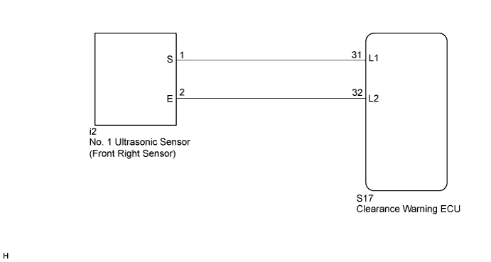
The No. 1 ultrasonic sensor (front right sensor) is installed on the front bumper.The clearance warning ECU detects obstacles based on signals received from the front right sensor. If the front right sensor circuit has an open, short or other malfunction, it will not function normally.
WIRING DIAGRAM
INSPECTION PROCEDURE
| 1.CHECK HARNESS AND CONNECTOR (CLEARANCE WARNING ECU - FRONT RIGHT SENSOR) |
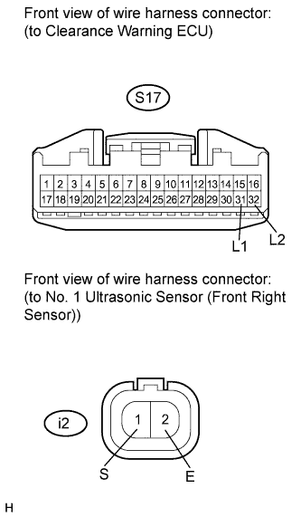
Disconnect the S17 connector from the clearance warning ECU.
Disconnect the i2 connector from the No. 1 ultrasonic sensor (front right sensor).
Measure the resistance according to the value(s) in the table below.
- Standard Resistance:
Tester Connection
| Condition
| Specified Condition
|
S17-31 (L1) - i2-1 (S)
| Always
| Below 1 Ω
|
S17-32 (L2) - i2-2 (E)
| Always
| Below 1 Ω
|
S17-31 (L1) - Body ground
| Always
| 10 kΩ or higher
|
S17-32 (L2) - Body ground
| Always
| 10 kΩ or higher
|
| | REPAIR OR REPLACE HARNESS OR CONNECTOR |
|
|
| 2.INSPECT NO. 1 ULTRASONIC SENSOR (FRONT RIGHT SENSOR) |
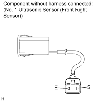
Remove the No. 1 ultrasonic sensor (front right sensor) (CAMRY_ACV40 RM000001PYF010X.html).
Measure the resistance according to the value(s) in the table below.
- Standard Resistance:
Tester Connection
| Condition
| Specified Condition
|
1 (S) - 2 (E)
| Always
| 8 to 12 kΩ
|