Toyota Parking Assist-Sensor System Reverse Signal Circuit
DESCRIPTION
WIRING DIAGRAM
INSPECTION PROCEDURE
INSPECT FUSE (GAUGE NO. 1)
CHECK CLEARANCE WARNING ECU (REVERSE SIGNAL INPUT)
CONFIRM MODEL
CHECK HARNESS AND CONNECTOR (CLEARANCE WARNING ECU - PARK/NEUTRAL POSITION SWITCH)
INSPECT PARK/NEUTRAL POSITION SWITCH
CHECK HARNESS AND CONNECTOR (CLEARANCE WARNING ECU - PARK/NEUTRAL POSITION SWITCH)
INSPECT PARK/NEUTRAL POSITION SWITCH
CHECK HARNESS AND CONNECTOR (CLEARANCE WARNING ECU - BACK-UP LIGHT SWITCH)
INSPECT BACK-UP LIGHT SWITCH
TOYOTA PARKING ASSIST-SENSOR SYSTEM - Reverse Signal Circuit |
DESCRIPTION
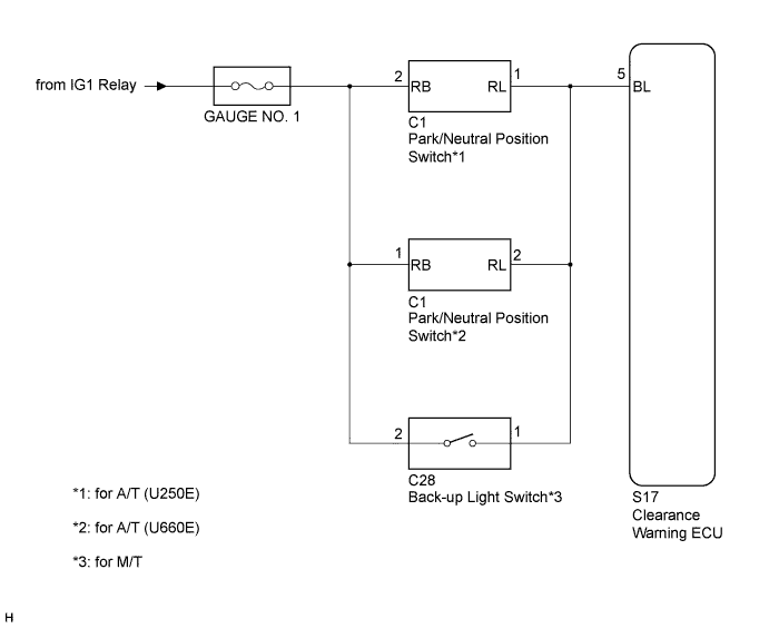
The clearance warning ECU receives the reverse signal from the park/neutral position switch (for A/T) or back-up light switch (for M/T).
WIRING DIAGRAM
INSPECTION PROCEDURE
| 1.INSPECT FUSE (GAUGE NO. 1) |
Remove the GAUGE NO. 1 fuse from the main body ECU (instrument panel junction block ).
Measure the resistance according to the value(s) in the table below.
- Standard Resistance:
Tester Connection
| Condition
| Specified Condition
|
GAUGE NO. 1 fuse
| Always
| Below 1 Ω
|
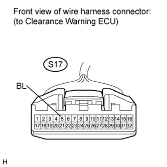
| 2.CHECK CLEARANCE WARNING ECU (REVERSE SIGNAL INPUT) |
Disconnect the S17 connector from the clearance warning ECU.
Measure the voltage according to the value(s) in the table below.
- Standard Voltage:
Tester Connection
| Condition
| Specified Condition
|
S17-5 (BL) - Body ground
| Ignition switch ON, shift lever in R
| 7 V or higher
|
Choose the model to be inspected.
- Result:
Model
| Proceed to
|
for A/T (U250E)
| A
|
for A/T (U660E)
| B
|
for M/T
| C
|
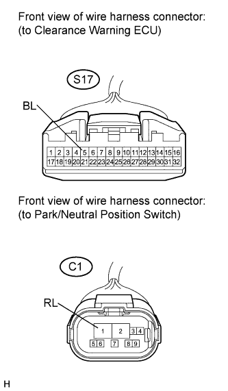
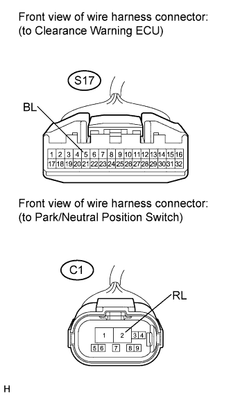
| 4.CHECK HARNESS AND CONNECTOR (CLEARANCE WARNING ECU - PARK/NEUTRAL POSITION SWITCH) |
Disconnect the S17 connector from the clearance warning ECU.
Disconnect the C1 connector from the park/neutral position switch.
Measure the resistance according to the value(s) in the table below.
- Standard Resistance:
Tester Connection
| Condition
| Specified Condition
|
S17-5 (BL) - C1-1 (RL)
| Always
| Below 1 Ω
|
S17-5 (BL) - Body ground
| Always
| 10 kΩ or higher
|
| | REPAIR OR REPLACE HARNESS OR CONNECTOR |
|
|
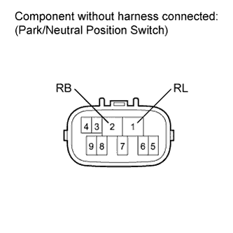
| 5.INSPECT PARK/NEUTRAL POSITION SWITCH |
Remove the park/neutral position switch (CAMRY_ACV40 RM000000YWR00WX.html).
Measure the resistance according to the value(s) in the table below.
- Standard Resistance:
Tester Connection
| Condition
| Specified Condition
|
1 (RL) - 2 (RB)
| Shift lever in R
| Below 1 Ω
|
1 (RL) - 2 (RB)
| Shift lever in any position except R
| 10 kΩ or higher
|
| OK |
|
|
|
| REPAIR OR REPLACE HARNESS OR CONNECTOR |
|
| 6.CHECK HARNESS AND CONNECTOR (CLEARANCE WARNING ECU - PARK/NEUTRAL POSITION SWITCH) |
Disconnect the S17 connector from the clearance warning ECU.
Disconnect the C1 connector from the park/neutral position switch.
Measure the resistance according to the value(s) in the table below.
- Standard Resistance:
Tester Connection
| Condition
| Specified Condition
|
S17-5 (BL) - C1-2 (RL)
| Always
| Below 1 Ω
|
S17-5 (BL) - Body ground
| Always
| 10 kΩ or higher
|
| | REPAIR OR REPLACE HARNESS OR CONNECTOR |
|
|
| 7.INSPECT PARK/NEUTRAL POSITION SWITCH |
Remove the park/neutral position switch (CAMRY_ACV40 RM0000016E101QX.html).
Measure the resistance according to the value(s) in the table below.
- Standard Resistance:
Tester Connection
| Condition
| Specified Condition
|
2 (RL) - 1 (RB)
| Shift lever in R
| Below 1 Ω
|
2 (RL) - 1 (RB)
| Shift lever in any position except R
| 10 kΩ or higher
|
| OK |
|
|
|
| REPAIR OR REPLACE HARNESS OR CONNECTOR |
|
| 8.CHECK HARNESS AND CONNECTOR (CLEARANCE WARNING ECU - BACK-UP LIGHT SWITCH) |
Disconnect the S17 connector from the clearance warning ECU.
Disconnect the C28 connector from the back-up light switch.
Measure the resistance according to the value(s) in the table below.
- Standard Resistance:
Tester Connection
| Condition
| Specified Condition
|
S17-5 (BL) - C28-1
| Always
| Below 1 Ω
|
S17-5 (BL) - Body ground
| Always
| 10 kΩ or higher
|
| | REPAIR OR REPLACE HARNESS OR CONNECTOR |
|
|
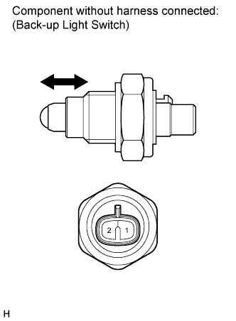
| 9.INSPECT BACK-UP LIGHT SWITCH |
Remove the back-up light switch.
Measure the resistance according to the value(s) in the table below.
- Standard Resistance:
Tester Connection
| Switch Condition
| Specified Condition
|
1 - 2
| Push
| Below 1 Ω
|
1 - 2
| Release
| 10 kΩ or higher
|
| | REPLACE BACK-UP LIGHT SWITCH |
|
|
| OK |
|
|
|
| REPAIR OR REPLACE HARNESS OR CONNECTOR |
|