Body Electrical. Camry. Acv40 Gsv40
Park Assist Monitoring. Camry. Acv40 Gsv40
Toyota Parking Assist-Sensor System -- Terminals Of Ecu |
| CLEARANCE WARNING ECU |

| Terminal No. (Symbol) | Wiring Color | Terminal Description | Condition | Specified Condition |
| S17-2 (P1) - S17-9 (E) | Y - W-B | Parking brake switch signal | Ignition switch ON, clearance sonar main switch ON, parking brake switch ON | Below 2 V |
| Ignition switch ON, clearance sonar main switch ON, parking brake switch OFF | 4.5 V or higher | |||
| S17-4 (+B) - S17-9 (E) | R - W-B | Corner sensor detection range adjusting terminal | Ignition switch ON, clearance sonar main switch ON | 11 to 14 V |
| S17-5 (BL) - S17-9 (E) | V - W-B | Reverse position signal | Ignition switch ON, shift lever in any position except R | Below 1.5 V |
| Ignition switch ON, shift lever in R | 7 V or higher | |||
| S17-6 (BGM1) - S17-9 (E) | P - W-B | Clearance warning buzzer (for corner sensor) signal | Clearance warning buzzer (for corner sensors) sounding | Pulse generation (See waveform 1) |
| S17-22 (BGM2) - S17-9 (E) | LG - W-B | Clearance warning buzzer (for back sensor) signal | Clearance warning buzzer (for back sensors) sounding | Pulse generation (See waveform 2) |
| S17-9 (E) - Body ground | W-B - Body ground | ECU ground | Always | Below 1 V |
| S17-10 (SPD) - S17-9 (E) | W - W-B | Vehicle speed signal | Ignition switch ON, drive wheels turning slowly | Pulse generation |
| S17-19 (CBZ) - S17-9 (E) | R - W-B | Clearance sonar main switch signal | Ignition switch off | Below 1 V |
| Ignition switch ON, clearance sonar main switch ON | 11 to 14 V | |||
| S17-21 (L8) - S17-9 (E) | O - W-B | Back sensor detection range switching terminal | Ignition switch ON, clearance sonar main switch ON, Back sensor detection range switching connector disconnected | Below 1 V |
| Ignition switch ON, clearance sonar main switch ON, Back sensor detection range switching connector connected | 11 to 14 V | |||
| S17-11 (E3) - Body ground | R - Body ground | Ground for ultrasonic sensor (Rear right center sensor) | Always | Below 1 V |
| S17-12 (S3) - S17-11 (E3) | L - R | Power source for ultrasonic sensor (Rear right center sensor) | Signals are transmitted from ECU to rear right center sensor (Sensor is not detecting an object) | Pulse generation (See waveform 3) |
| S17-14 (E5) - Body ground | W - Body ground | Ground for ultrasonic sensor (Rear left sensor) | Always | Below 1 V |
| S17-13 (S2) - S17-14 (E5) | G - W | Power source for ultrasonic sensor (Rear left sensor) | Signals are transmitted from ECU to rear left sensor (Sensor is not detecting an object) | Pulse generation (See waveform 4) |
| S17-16 (E10) - Body ground | P - Body ground | Ground for ultrasonic sensor (Rear right sensor) | Always | Below 1 V |
| S17-15 (S1) - S17-16 (E10) | B - P | Power source for ultrasonic sensor (Rear right sensor) | Signals are transmitted from ECU to rear right sensor (Sensor is not detecting an object) | Pulse generation (See waveform 4) |
| S17-27 (E4) - Body ground | V - Body ground | Ground for ultrasonic sensor (Rear left center sensor) | Always | Below 1 V |
| S17-28 (S4) - S17-27 (E4) | O - V | Power source for ultrasonic sensor (Rear left center sensor) | Signals are transmitted from ECU to rear left center sensor (Sensor is not detecting an object) | Pulse generation (See waveform 3) |
| S17-30 (L4) - Body ground | G - Body ground | Ground for ultrasonic sensor (Front left sensor) | Always | Below 1 V |
| S17-29 (L3) - S17-30 (L4) | B - G | Power source for ultrasonic sensor (Front left sensor) | Signals are transmitted from ECU to front left sensor (Sensor is not detecting an object) | Pulse generation (See waveform 4) |
| S17-32 (L2) - Body ground | BR - Body ground | Ground for ultrasonic sensor (Front right sensor) | Always | Below 1 V |
| S17-31 (L1) - S17-32 (L2) | GR - BR | Power source for ultrasonic sensor (Front right sensor) | Signals are transmitted from ECU to front right sensor (Sensor is not detecting an object) | Pulse generation (See waveform 4) |
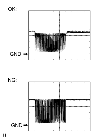
Using an oscilloscope, check waveform 1.
Waveform 1 (Reference)
Item Content Terminal No. (Symbol) S17-6 (BGM1) - S17-9 (E) Tool Setting 2 V/DIV., 200 μsec./DIV. Vehicle Condition When corner sonar detects obstacle (buzzer sounds)
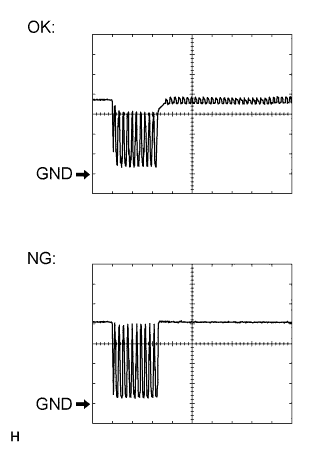
Using an oscilloscope, check waveform 2.
Waveform 2 (Reference)
Item Content Terminal No. (Symbol) S17-22 (BGM2) - S17-9 (E) Tool Setting 2 V/DIV., 200 μsec./DIV. Vehicle Condition When back sonar detects obstacle (buzzer sounds)
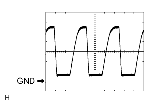
Using an oscilloscope, check waveform 3.
Waveform 3 (Reference)
Item Content Terminal No. (Symbol) S17-13(S2) - S17-14 (E5)
S17-15 (S1) - S17-16 (E10)
S17-29 (L3) - S17-30 (L4)
S17-31 (L1) - S17-32 (L2)Tool Setting 2 V/DIV., 100 μsec./DIV. Vehicle Condition Signals are transmitted from ECU to sensor (Sensor is not detecting an object)
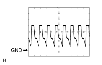
Using an oscilloscope, check waveform 4.
Waveform 4 (Reference)
Item Content Terminal No. (Symbol) S17-12 (S3) - S17-11 (E3)
S17-28 (S4) - S17-27 (E4)Tool Setting 2 V/DIV., 100 μsec./DIV. Vehicle Condition Signals are transmitted from ECU to sensor (Sensor is not detecting an object)