Navigation System Speaker Circuit
DESCRIPTION
WIRING DIAGRAM
INSPECTION PROCEDURE
CHECK HARNESS AND CONNECTOR
INSPECT FRONT NO. 1 SPEAKER
INSPECT FRONT NO. 2 SPEAKER
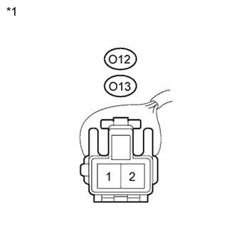
INSPECT REAR SPEAKER
NAVIGATION SYSTEM - Speaker Circuit |
DESCRIPTION
- If there is a short in this circuit, the navigation receiver assembly detects it and stops output to the speakers.
- Thus sound cannot be heard from the speakers even if there is no malfunction in the navigation receiver assembly or speakers.
- If a short is detected in the speaker circuit, no sound can be heard from the speakers.
WIRING DIAGRAM
INSPECTION PROCEDURE
| 1.CHECK HARNESS AND CONNECTOR |
Disconnect the navigation receiver assembly connector.
Disconnect the navigation receiver assembly connector.
Disconnect the front No. 1 speaker connectors.
Disconnect the front No. 2 speaker connectors.
Disconnect the rear speaker connectors.
Measure the resistance between each of the front No. 2 speakers and the navigation receiver assembly to check for an open circuit in the wire harness.
- Standard Resistance:
Tester Connection
| Condition
| Specified Condition
|
F27-2 (FL+) - F21-2 (TWL+)
| Always
| Below 1 Ω
|
F27-6 (FL-) - F21-4 (TWL-)
| Always
| Below 1 Ω
|
F27-1 (FR+) - F23-2 (TWR+)
| Always
| Below 1 Ω
|
F27-5 (FR-) - F23-4 (TWR-)
| Always
| Below 1 Ω
|
Measure the resistance between each of the front No. 2 speakers and the front No. 1 speakers to check for an open circuit in the wire harness.
- Standard Resistance:
Tester Connection
| Condition
| Specified Condition
|
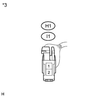
F21-1 (+) - I1-1
| Always
| Below 1 Ω
|
F21-3 (-) - I1-2
| Always
| Below 1 Ω
|
F23-1 (+) - H1-1
| Always
| Below 1 Ω
|
F23-3 (-) - H1-2
| Always
| Below 1 Ω
|
Measure the resistance between each of the rear speakers and the navigation receiver assembly to check for an open circuit in the wire harness.
- Standard Resistance:
Tester Connection
| Condition
| Specified Condition
|
F28-2 (RL+) - O12-1
| Always
| Below 1 Ω
|
F28-6 (RL-) - O12-2
| Always
| Below 1 Ω
|
F28-1 (RR+) - O13-1
| Always
| Below 1 Ω
|
F28-3 (RR-) - O13-2
| Always
| Below 1 Ω
|
Measure the resistance between each speaker and body ground to check for a short circuit in the wire harness.
- Standard Resistance:
Tester Connection
| Condition
| Specified Condition
|
F21-1 (+) - Body ground
| Always
| 10 kΩ or higher
|
F21-3 (-) - Body ground
| Always
| 10 kΩ or higher
|
F21-2 (TWL+) - Body ground
| Always
| 10 kΩ or higher
|
F21-4 (TWL-) - Body ground
| Always
| 10 kΩ or higher
|
F23-1 (+) - Body ground
| Always
| 10 kΩ or higher
|
F23-3 (-) - Body ground
| Always
| 10 kΩ or higher
|
F23-2 (TWR+) - Body ground
| Always
| 10 kΩ or higher
|
F23-4 (TWR-) - Body ground
| Always
| 10 kΩ or higher
|
O12-1 - Body ground
| Always
| 10 kΩ or higher
|
O12-2 - Body ground
| Always
| 10 kΩ or higher
|
O13-1 - Body ground
| Always
| 10 kΩ or higher
|
O13-2 - Body ground
| Always
| 10 kΩ or higher
|
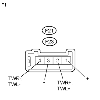
Text in Illustration*1
| Front view of wire harness connector
(to Navigation Receiver Assembly)
|
*2
| Front view of wire harness connector
(to Navigation Receiver Assembly)
|
*3
| Front view of wire harness connector
(to Front No. 1 Speaker)
|
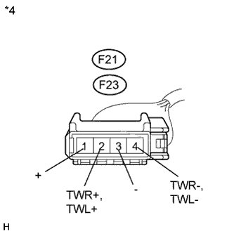
*4
| Front view of wire harness connector
(to Front No. 2 Speaker)
|
*5
| Front view of wire harness connector
(to Rear Speaker)
|
| | REPAIR OR REPLACE HARNESS OR CONNECTOR |
|
|
| 2.INSPECT FRONT NO. 1 SPEAKER |
Resistance check
Measure the resistance between the terminals of the speaker.
- Standard Resistance:
Tester Connection
| Condition
| Specified Condition
|
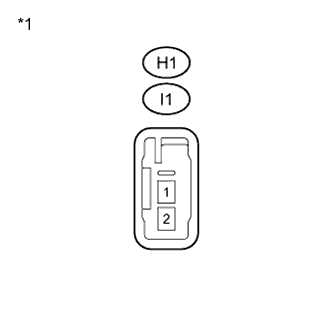
I1-1 - I1-2
| Always
| 3.4 to 4.6 Ω
|
H1-1 - H1-2
| Always
| 3.4 to 4.6 Ω
|
- NOTICE:
- The speaker should not be removed to check resistance.
Text in Illustration*1
| Component without harness connected
(Front No. 1 Speaker)
|
| 3.INSPECT FRONT NO. 2 SPEAKER |
Resistance check
Measure the resistance between the terminals of the speaker.
- Standard Resistance:
Tester Connection
| Condition
| Specified Condition
|
F21-1 (+) - F21-2 (TWL+)
| Always
| Below 1 Ω
|
F21-3 (-) - F21-4 (TWL-)
| Always
| Below 1 Ω
|
F23-1 (+) - F23-2 (TWR+)
| Always
| Below 1 Ω
|
F23-3 (-) - F23-4 (TWR-)
| Always
| Below 1 Ω
|
- NOTICE:
- The speaker should not be removed to check resistance.
Text in Illustration*1
| Component without harness connected
(Front No. 2 Speaker)
|
Check that the malfunction disappears when another speaker in good condition is installed.
- Standard:
- Malfunction disappears.
- HINT:
- Connect all the connectors to the front No. 2 speakers.
- If there is a possibility that either the right or left front speaker is defective, inspect by interchanging the right one with the left one.
- Perform the above inspection on both LH and RH sides.
Resistance check
Measure the resistance between the terminals of the speaker.
- Standard Resistance:
Tester Connection
| Condition
| Specified Condition
|
O12-1 - O12-2
| Always
| 3.2 to 4.8 Ω
|
O13-1 - O13-2
| Always
| 3.2 to 4.8 Ω
|
- NOTICE:
- The speaker should not be removed to check resistance.
Text in Illustration*1
| Component without harness connected
(Rear Speaker)
|