Audio And Visual System Vehicle Speed Signal Circuit Between Radio Receiver And Combination Meter
DESCRIPTION
WIRING DIAGRAM
INSPECTION PROCEDURE
CHECK COMBINATION METER
CHECK HARNESS AND CONNECTOR (COMBINATION METER - RADIO RECEIVER)
CHECK HARNESS AND CONNECTOR (RADIO RECEIVER - NO. 3 JUNCTION BLOCK)
AUDIO AND VISUAL SYSTEM - Vehicle Speed Signal Circuit between Radio Receiver and Combination Meter |
DESCRIPTION
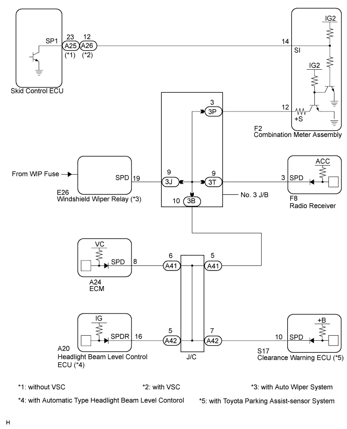
This circuit is necessary for the ASL (Auto Sound Leveliser) built into the radio receiver.Speed signals are received from the combination meter and used for the ASL.The ASL function automatically adjusts the sound data in order to enable to hear the clear audio sound even when vehicle noise increases (as vehicle noise increases, the volume is turned up etc.).- HINT:
- A voltage of 12 V or 5 V is output from each ECU and then input to the combination meter. The signal is changed to a pulse signal at the transistor in the combination meter. Each ECU controls the respective system based on the pulse signal.
- If a short occurs in an ECU, all systems in the diagram below will not operate normally.
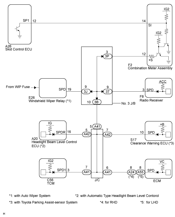
WIRING DIAGRAM
INSPECTION PROCEDURE
| 1.CHECK COMBINATION METER |
Inspect the circuits that send vehicle speed signals to the meter / gauge system (CAMRY_ACV40 RM000002UD700ZX.html).
During the inspection, if there is an instruction that indicates to go back to inspections for each system, proceed to the next step.
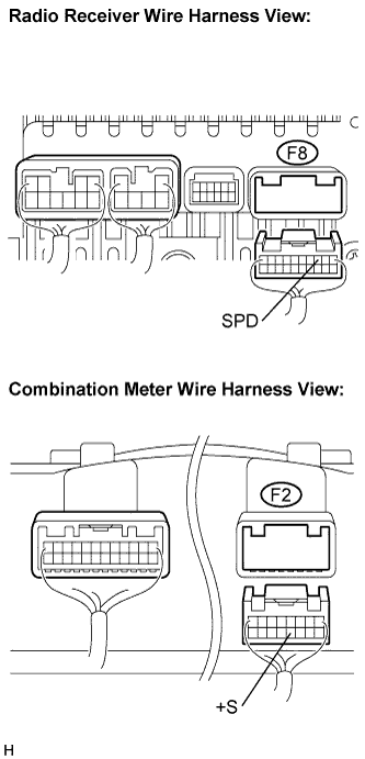
| 2.CHECK HARNESS AND CONNECTOR (COMBINATION METER - RADIO RECEIVER) |
Disconnect the F2 connector from the combination meter assembly and the F8 connector from the radio receiver.
Measure the resistance according to the value(s) in the table below.
- Standard Resistance:
Tester Connection
| Condition
| Specified Condition
|
F8-3 (SPD) - F2-12 (+S)
| Always
| Below 1 Ω
|
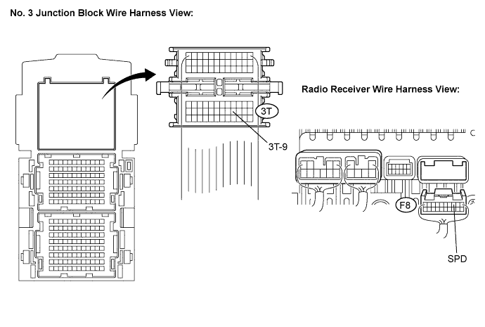
| 3.CHECK HARNESS AND CONNECTOR (RADIO RECEIVER - NO. 3 JUNCTION BLOCK) |
Disconnect the F8 connector from the radio receiver.
Disconnect the No. 3 junction block connector.
Measure the resistance according to the value(s) in the table below.
- Standard Resistance:
Tester Connection
| Condition
| Specified Condition
|
F8-3 (SPD) - 3T-9
| Always
| Below 1 Ω
|
| | REPAIR OR REPLACE HARNESS OR CONNECTOR (RADIO RECEIVER - NO. 3 JUNCTION BLOCK) |
|
|
| OK |
|
|
|
| REPAIR OR REPLACE HARNESS OR CONNECTOR (NO. 3 JUNCTION BLOCK) |
|