Meter. Camry. Acv40 Gsv40
DESCRIPTION
WIRING DIAGRAM
INSPECTION PROCEDURE
INSPECT COMBINATION METER ASSEMBLY (OUTPUT WAVEFORM)
INSPECT ECU TERMINAL VOLTAGE (INPUT VOLTAGE)
INSPECT COMBINATION METER ASSEMBLY (OUTPUT VOLTAGE)
INSPECT SKID CONTROL ECU (INPUT WAVEFORM)
CHECK HARNESS AND CONNECTOR (COMBINATION METER - SKID CONTROL ECU)
CHECK HARNESS AND CONNECTOR (COMBINATION METER - NO. 3 JUNCTION BLOCK)
CHECK HARNESS AND CONNECTOR (NO. 3 JUNCTION BLOCK)
SYSTEM CHECK
CHECK HARNESS AND CONNECTOR (RADIO RECEIVER CIRCUIT)
CHECK HARNESS AND CONNECTOR (WINDSHIELD WIPER REPLAY CIRCUIT)
SYSTEM CHECK
CHECK HARNESS AND CONNECTOR (ECM CIRCUIT)
CHECK HARNESS AND CONNECTOR (HEADLIGHT LEVELING ECU CIRCUIT)
CHECK HARNESS AND CONNECTOR (TCM CIRCUIT)
CHECK HARNESS AND CONNECTOR (CLEARANCE WARNING ECU CIRCUIT)
METER / GAUGE SYSTEM - Speed Signal Circuit |
DESCRIPTION
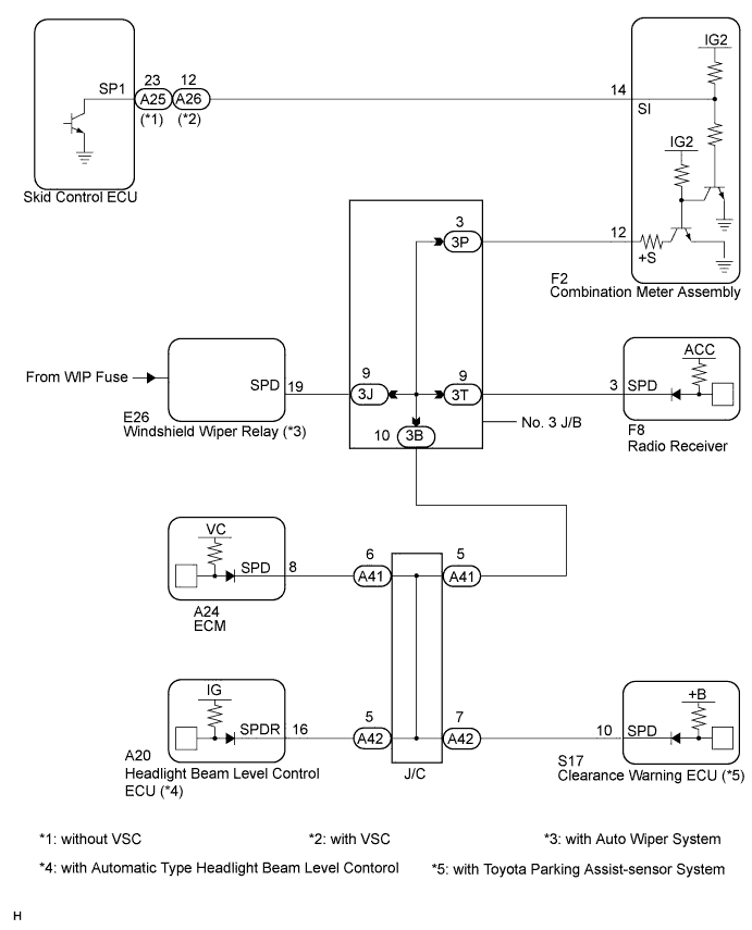
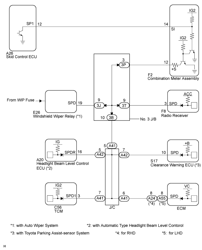
The meter CPU receives vehicle speed signals from this circuit. The vehicle speed sensor detects the voltage that varies according to the vehicle speed. The skid control ECU supplies power to the vehicle speed sensor. The skid control ECU detects vehicle speed signals based on the pulses of the voltage. The skid control ECU transmits vehicle speed signals as pulses to the meter CPU. A voltage of 12 V is output from the combination meter assembly and then input to the skid control ECU. The signal is changed to a pulse signal at the transistor in the combination meter assembly.A voltage of 12 V or 5 V is output from each ECU or relay and then input to the combination meter assembly.Each ECU controls the respective system based on the pulse signal.- HINT:
- This circuit is used for another system, and is not used for combination meter operation.
WIRING DIAGRAM
INSPECTION PROCEDURE
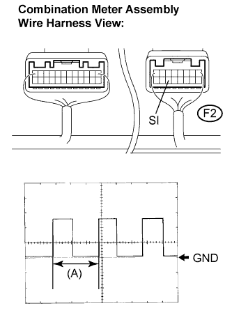
| 1.INSPECT COMBINATION METER ASSEMBLY (OUTPUT WAVEFORM) |
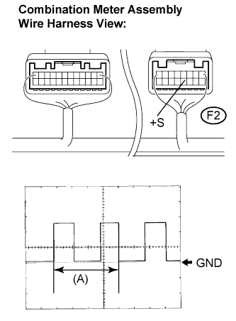
Check the output waveform.
Remove the combination meter assembly with connector(s) still connected.
Connect the oscilloscope to the terminals F2-12 (+S) and body ground.
Turn the ignition switch to the ON position.
Turn the wheel slowly.
Check the signal waveform according to the condition(s) in the table below.
Item
| Condition
|
Tool setting
| 5 V/DIV., 20 ms./DIV.
|
Vehicle condition
| Driving at approx. 20 km/h (12 mph)
|
- OK:
- The waveform is displayed as shown in the illustration.
- HINT:
- When the system is functioning normally, one wheel revolution generates 4 pulses. As the vehicle speed increases, the width indicated by (A) in the illustration narrows.
| OK |
|
|
|
| RETURN TO THE ORIGINAL INSPECTION FOR OTHER SYSTEM |
|
| 2.INSPECT ECU TERMINAL VOLTAGE (INPUT VOLTAGE) |
Remove the F2 connector.
Measure the voltage according to the value(s) in the table below.
- Standard voltage:
Tester Connection
| Condition
| Specified Condition
|
F2-12 (+S) - Body ground
| Turn the ignition switch to the ON position
| 4.5 to 14 V
|
- HINT:
- If any of the ECUs specified in the wiring diagram supplied power to the combination meter, the combination meter will output a waveform.
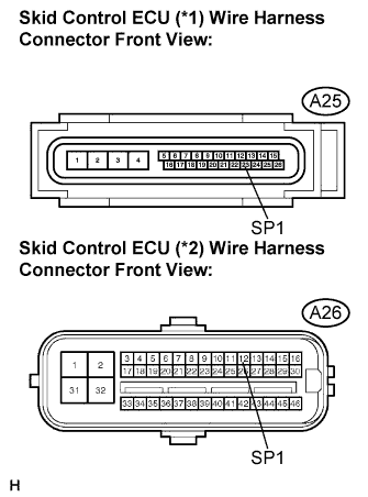
| 3.INSPECT COMBINATION METER ASSEMBLY (OUTPUT VOLTAGE) |
Remove the A25 (*1)/A26 (*2) connector.
Measure the voltage according to the value(s) in the table below.
- Standard voltage:
Tester Connection
| Condition
| Specified Condition
|
A25-23 (SP1) (*1) - Body ground
| Turn the ignition switch to the ON position
| 10 to 14 V
|
A26-12 (SP1) (*2) - Body ground
| Turn the ignition switch to the ON position
| 10 to 14 V
|
*1: without VSC
*2: with VSC
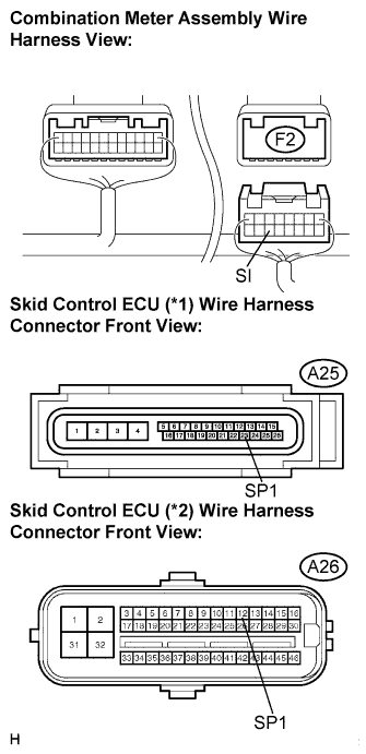
| 4.INSPECT SKID CONTROL ECU (INPUT WAVEFORM) |
Check the input waveform.
Reconnect the A25 (*1)/A26 (*2) connector.
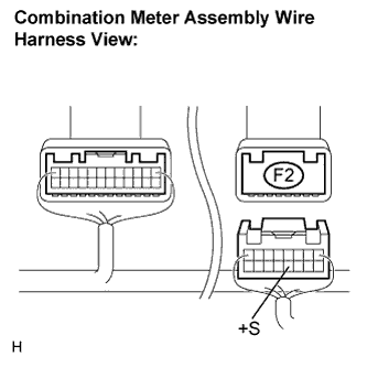
Remove the combination meter assembly with connector(s) still connected.
Connect the oscilloscope to the terminals F2-14 (SI) and body ground.
Turn the ignition switch to the ON position.
Turn the wheel slowly.
Check the signal waveform according to the condition(s) in the table below.
Item
| Condition
|
Tool setting
| 5 V/DIV., 20 ms./DIV.
|
Vehicle condition
| Driving at approx. 20 km/h (12 mph)
|
- OK:
- The waveform is displayed as shown in the illustration.
- HINT:
- When the system is functioning normally, one wheel revolution generates 4 pulses. As the vehicle speed increases, the width indicated by (A) in the illustration narrows.
- *1: without VSC
- *2: with VSC
| OK |
|
|
|
| REPLACE COMBINATION METER ASSEMBLY |
|
| 5.CHECK HARNESS AND CONNECTOR (COMBINATION METER - SKID CONTROL ECU) |
Disconnect the F2 connector.
Measure the resistance according to the value(s) in the table below.
- Standard resistance:
Tester Connection
| Condition
| Specified Condition
|
A25-23 (SP1) (*1) - F2-14 (SI)
| Always
| Below 1 Ω
|
A25-23 (SP1) (*1) - Body ground
| Always
| 10 kΩ or higher
|
A26-12 (SP1) (*2) - F2-14 (SI)
| Always
| Below 1 Ω
|
A26-12 (SP1) (*2) - Body ground
| Always
| 10 kΩ or higher
|
*1: without VSC
*2: with VSC
| | REPAIR OR REPLACE HARNESS OR CONNECTOR |
|
|
| OK |
|
|
|
| REPLACE COMBINATION METER ASSEMBLY |
|
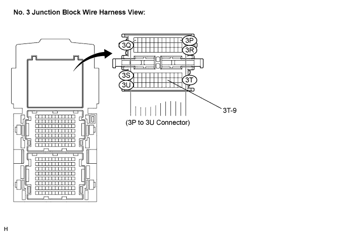
| 6.CHECK HARNESS AND CONNECTOR (COMBINATION METER - NO. 3 JUNCTION BLOCK) |
Disconnect the 3P to 3U No. 3 junction block connector.
Measure the resistance according to the value(s) in the table below.
- Standard resistance:
Tester Connection
| Condition
| Specified Condition
|
F2-12 (+S) - 3P-3
| Always
| Below 1 Ω
|
F2-12 (+S) - Body ground
| Always
| 10 kΩ or higher
|
| | REPAIR OR REPLACE HARNESS OR CONNECTOR |
|
|
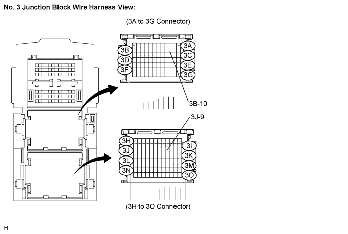
| 7.CHECK HARNESS AND CONNECTOR (NO. 3 JUNCTION BLOCK) |
Inspect for a short in the circuit that connected the No. 3 junction block shown in the wiring diagram.
- HINT:
- If voltage is not present, the circuit (ECU) was possibly the malfunctioning circuit, This is the circuit that will be diagnosed by following the A step that follows.
Disconnect the 3H to 3O and 3A to 3H No. 3 junction block connectors.
Measure the voltage according to the value(s) in the table below.
- Standard voltage:
Tester Connection
| Condition
| Specified Condition
|
3B-10 - Body ground
| Turn the ignition switch to the ON position
| 4.5 to 14 V
|
3J-9 - Body ground
| Turn the ignition switch to the ON position
| 4.5 to 14 V
|
Reconnect the 3H to 3O No. 3 junction block connectors.
Measure the voltage according to the value(s) in the table below.
- Standard voltage:
Tester Connection
| Condition
| Specified Condition
|
3T-9 - Body ground
| Turn the ignition switch to the ON position
| 4.5 to 14 V
|
- Result:
Result
| Proceed to
|
Voltage is not present in one circuit
| A
|
Voltage is present in all the circuit.
| B
|
| | REPAIR OR REPLACE HARNESS OR CONNECTOR (NO. 3 JUNCTION BLOCK) |
|
|
Select the circuit in which is not present voltage in step 7.
- Result:
Tester Connection
| System that uses the circuit
| Proceed to
|
3T-9 - Body ground
| Audio/Visual System
| A
|
3J-9 - Body ground
| Wiper and Washer System
| B
|
3B-10 - Body ground
| SFI System
| C
|
3B-10 - Body ground
| Lighting System
| C
|
3B-10 - Body ground
| Automatic Transaxle System
| C
|
3B-10 - Body ground
| Toyota Parking Assist-sensor System
| C
|
| 9.CHECK HARNESS AND CONNECTOR (RADIO RECEIVER CIRCUIT) |
Disconnect the F8 connector.
Measure the resistance according to the value(s) in the table below.
- Standard resistance:
Tester Connection
| Condition
| Specified Condition
|
F8-5 (SPD) - Body ground
| Always
| 10 kΩ or higher
|
| | REPAIR OR REPLACE HARNESS OR CONNECTOR |
|
|
| OK |
|
|
|
| REPLACE RADIO RECEIVER ASSEMBLY |
|
| 10.CHECK HARNESS AND CONNECTOR (WINDSHIELD WIPER REPLAY CIRCUIT) |
Disconnect the E26 connector.
Measure the resistance according to the value(s) in the table below.
- Standard resistance:
Tester Connection
| Condition
| Specified Condition
|
E26-19 (SPD) - Body ground
| Always
| 10 kΩ or higher
|
| | REPAIR OR REPLACE HARNESS OR CONNECTOR |
|
|
| OK |
|
|
|
| REPLACE WINDSHIELD WIPER RELAY |
|
Select the system in which is not present voltage in step 7.
- Result:
Tester Connection
| System that uses the circuit
| Proceed to
|
3B-10 - Body ground
| SFI System
| A
|
3B-10 - Body ground
| Lighting System
| B
|
3B-10 - Body ground
| Automatic Transaxle System
| C
|
3B-10 - Body ground
| Toyota Parking Assist-sensor System
| D
|
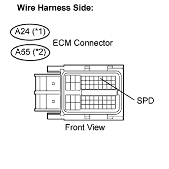
| 12.CHECK HARNESS AND CONNECTOR (ECM CIRCUIT) |
Disconnect the A24 (*1) or A55 (*2) connector.
Measure the resistance according to the value(s) in the table below.
- Standard resistance:
Tester Connection
| Condition
| Specified Condition
|
A24-8 (SPD) (*1) - Body ground
| Always
| 10 kΩ or higher
|
A55-8 (SPD) (*2) - Body ground
| Always
| 10 kΩ or higher
|
*1: for 2AZ-FE, or RHD for 2GR-FE
*2: LHD for 2GR-FE
| | REPAIR OR REPLACE HARNESS OR CONNECTOR |
|
|
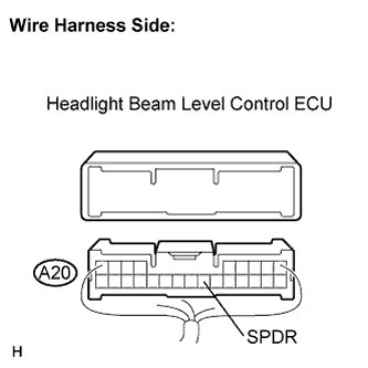
| 13.CHECK HARNESS AND CONNECTOR (HEADLIGHT LEVELING ECU CIRCUIT) |
Disconnect the A20 connector.
Measure the resistance according to the value(s) in the table below.
- Standard resistance:
Tester Connection
| Condition
| Specified Condition
|
A20-16 (SPDR) - Body ground
| Always
| 10 kΩ or higher
|
| | REPAIR OR REPLACE HARNESS OR CONNECTOR |
|
|
| OK |
|
|
|
| REPLACE HEADLIGHT LEVELING ECU |
|
| 14.CHECK HARNESS AND CONNECTOR (TCM CIRCUIT) |
Disconnect the C56 connector.
Measure the resistance according to the value(s) in the table below.
- Standard resistance:
Tester Connection
| Condition
| Specified Condition
|
C56-3 (SPD1) - Body ground
| Always
| 10 kΩ or higher
|
| | REPAIR OR REPLACE HARNESS OR CONNECTOR |
|
|
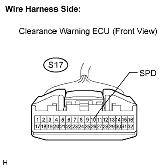
| 15.CHECK HARNESS AND CONNECTOR (CLEARANCE WARNING ECU CIRCUIT) |
Disconnect the S17 connector.
Measure the resistance according to the value(s) in the table below.
- Standard resistance:
Tester Connection
| Condition
| Specified Condition
|
S17-10 (SPD) - Body ground
| Always
| 10 kΩ or higher
|
| | REPAIR OR REPLACE HARNESS OR CONNECTOR |
|
|
| OK |
|
|
|
| REPLACE CLEARANCE WARNING ECU |
|