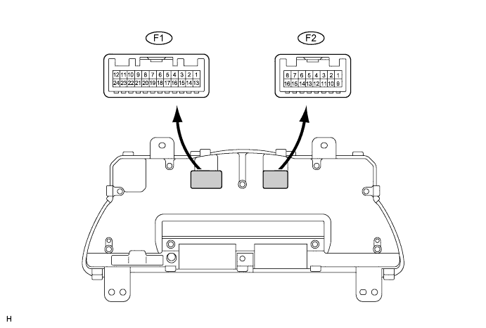
Symbols (Terminal No.)
| Wiring Color
| Terminal Description
| Condition
| Specified Condition
|
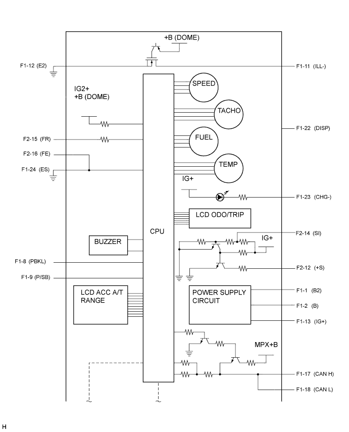
B (F1-1) - Body ground
| L - Body ground
| Battery
| Always
| 10 to 14 V
|
B2 (F1-2) - Body ground
| V - Body ground
| Battery
| Always
| 10 to 14 V
|
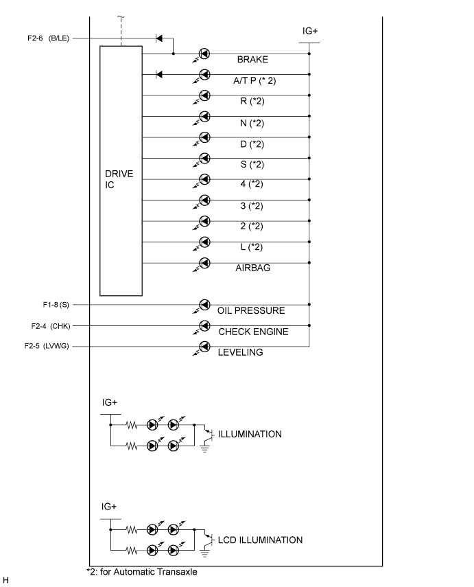
S (F1-8) - Body ground
| O - Body ground
| Engine oil pressure warning light signal
| Turn the ignition switch to the ON position, engine oil pressure warning light OFF
| 10 to 14 V
|
Turn the ignition switch to the ON position, engine oil pressure warning light ON
| Below 1 V
|
P/SB (F1-9) - Body ground
| G - Body ground
| Passenger seat belt warning light signal
| Sit on the front passenger seat, turn the ignition switch to the ON position, front passenger seat belt warning light OFF
| 10 to 14 V
|
Sit on the front passenger seat, turn the ignition switch to the ON position, front passenger seat belt warning light Blinks
| 10 to 14 V ←→ Below 1 V
|
ILL- (F1-11) - Body ground
| BR - Body ground
| Illumination signal
| Turn the ignition switch to the ON position
| 10 to 14 V ←→ Below 1 V
|
FE (F1-12) - Body ground
| W-B - Body ground
| Ground (Power ground)
| Always
| Below 1 V
|
IG+ (F1-13) - Body ground
| GR - Body ground
| Ignition switch signal
| Turn the ignition switch off
| Below 1 V
|
Turn the ignition switch to the ON position
| 10 to 14 V
|
CANL (F1-17) - Body ground
| B - Body ground
| CAN communication signal
| -
| -
|
CANH (F1-18) - Body ground
| W - Body ground
| CAN communication signal
| -
| -
|
DISP (F1-22) - Body ground
| V - Body ground
| Steering pad switch signal
| Turn the ignition switch to the ON position, DISP switch off
| 4 to 6 V
|
Turn the ignition switch to the ON position, DISP switch ON
| Below 1 V
|
CHG- (F1-23) - Body ground
| L - Body ground
| Charge warning light signal
| Turn the ignition switch to the ON position, CHARGE warning light OFF
| 10 to 14 V
|
Turn the ignition switch to the ON position, CHARGE warning light ON
| Below 1 V
|
ES (F1-24) - Body ground
| BR - Body ground
| Ground (Signal ground)
| Always
| Below 1 V
|
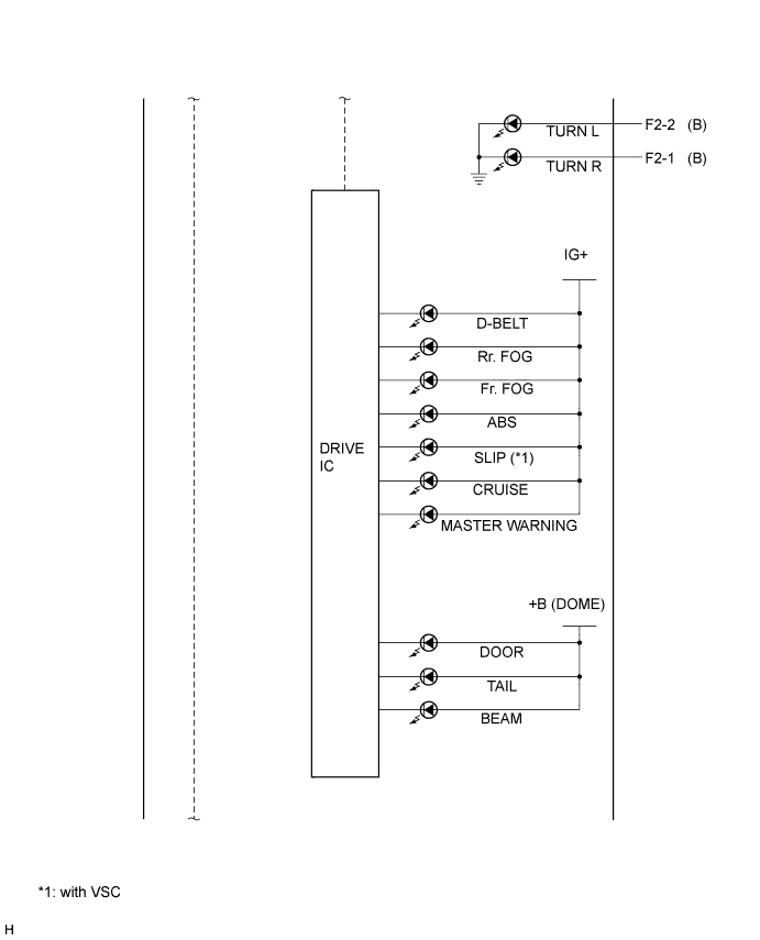
B (F2-1) - Body ground
| G - Body ground
| Turn indicator light signal
| Turn the ignition switch to the ON position, turn signal RH indicator light OFF
| Below 1 V
|
Turn the ignition switch to the ON position, turn signal RH indicator light ON
| 10 to 14 V
|
B (F2-2) - Body ground
| B - Body ground
| Turn indicator light signal
| Turn the ignition switch to the ON position, turn signal LH indicator light OFF
| Below 1 V
|
Turn the ignition switch to the ON position, turn signal LH indicator light ON
| 10 to 14 V
|
CHK (F2-4) - Body ground
| R - Body ground
| Check engine warning light signal
| Turn the ignition switch to the ON position, CHECK ENGINE warning light ON
| Below 3 V
|
Turn the ignition switch to the ON position, CHECK ENGINE warning light OFF
| 10 to 14 V
|
LVWG (F2-5) - Body ground
| SB - Body ground
| Headlight beam level control indicator light signal
| Turn the ignition switch to the ON position, LEVELING indicator light OFF
| 10 to 14 V
|
Turn the ignition switch to the ON position, LEVELING indicator light ON
| Below 2 V
|
B/LE (F2-6) - Body ground
| LG - Body ground
| Brake fluid level warning light signal
| Turn the ignition switch to the ON position, BRAKE warning light OFF
| 10 to 14 V
|
Turn the ignition switch to the ON position, BRAKE warning light ON
| Below 1 V
|
PBKL (F2-8) - Body ground
| BR - Body ground
| Front passenger seat buckle switch signal
| Turn the ignition switch to the ON position, front passenger seat belt is unfastened
| Below 1 V
|
Turn the ignition switch to the ON position, front passenger seat belt is fastened
| 10 to 14 V
|
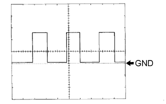
+S (F2-12) - Body ground
| V - Body ground
| Speed signal for other systems (Output)
| Turn the wheel slowly
| Pulse generation (See waveform 1)
|
SI (F2-14) - Body ground
| V - Body ground
| Speed signal for other systems (Input)
| Turn the ignition switch to the ON position, turn the wheel slowly
| Pulse generation (See waveform 1)
|
FR (F2-15) - Body ground
| GR - Body ground
| Fuel signal
| Turn the ignition switch to the ON position, fuel level is FULL
| Below 1 V
|
Turn the ignition switch to the ON position, fuel level is EMPTY
| 3 to 7 V
|
FE (F2-16) - Body ground
| P - Body ground
| Ground (Fuel ground)
| Always
| Below 1 V
|