Key Reminder Warning System Unlock Warning Switch Circuit
DESCRIPTION
WIRING DIAGRAM
INSPECTION PROCEDURE
READ VALUE USING INTELLIGENT TESTER
INSPECT UNLOCK WARNING SWITCH ASSEMBLY
CHECK HARNESS AND CONNECTOR (UNLOCK WARNING SWITCH - MAIN BODY ECU)
CHECK HARNESS AND CONNECTOR (UNLOCK WARNING SWITCH - BODY GROUND)
KEY REMINDER WARNING SYSTEM - Unlock Warning Switch Circuit |
DESCRIPTION
The unlock warning switch detects if the key is in the ignition key cylinder.The unlock warning switch turns on when the key is inserted into the ignition key cylinder and turns off when the key is removed from the cylinder. The main body ECU is connected to the unlock warning switch via terminal KSW and key detection status signals are input to the main body ECU.The main body ECU applies voltage to the unlock warning switch via terminal KSW. When the unlock warning switch is on (there is continuity between the switch terminals), a signal indicating that the key is in the ignition key cylinder is input to the main body ECU. When the switch is off (there is no continuity between the switch terminals), a signal indicating that the key is not in the cylinder is input.
WIRING DIAGRAM
INSPECTION PROCEDURE
| 1.READ VALUE USING INTELLIGENT TESTER |
Connect the intelligent tester to the DLC3.
Turn the ignition switch to the ON position and turn the intelligent tester main switch on.
Select Key Unlock Warning SW in the DATA LIST and read the value displayed on the tester.
BODY:Tester Display
| Measurement Item/Range
| Normal Condition
| Diagnostic Note
|
Key Unlock Warning SW
| Unlock warning switch signal
/ON or OFF
| ON: Key is in ignition key cylinder
OFF: No key is in ignition key cylinder
| -
|
- OK:
- ON (Key is in ignition key cylinder) appears on the screen.
| | PROCEED TO NEXT CIRCUIT INSPECTION SHOWN IN PROBLEM SYMPTOMS TABLE |
|
|
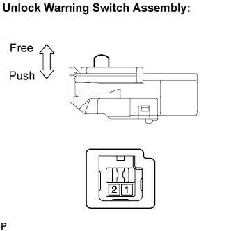
| 2.INSPECT UNLOCK WARNING SWITCH ASSEMBLY |
Remove the unlock warning switch assembly (CAMRY_ACV40 RM0000026TU00RX.html).
Measure the resistance according to the value(s) in the table below.
- Standard resistance:
Tester Connection
| Condition
| Specified Condition
|
1 - 2
| Switch free (Key removed)
| 10 kΩ or higher
|
1 - 2
| Switch pushed (Key set)
| Below 1 Ω
|
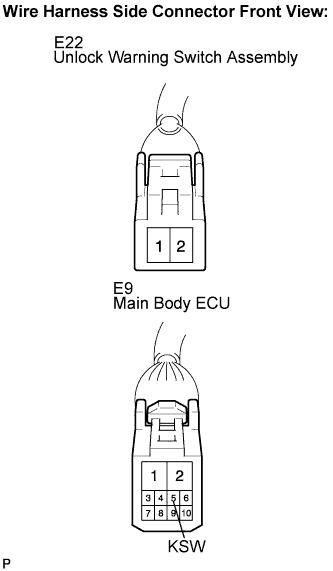
| 3.CHECK HARNESS AND CONNECTOR (UNLOCK WARNING SWITCH - MAIN BODY ECU) |
Disconnect the E22 switch and E9 ECU connectors.
Measure the resistance according to the value(s) in the table below.
- Standard resistance:
Tester Connection
| Condition
| Specified Condition
|
E22-1 - E9-5 (KSW)
| Always
| Below 1 Ω
|
E22-1 - Body ground
| 10 kΩ or higher
|
| | REPAIR OR REPLACE HARNESS OR CONNECTOR |
|
|
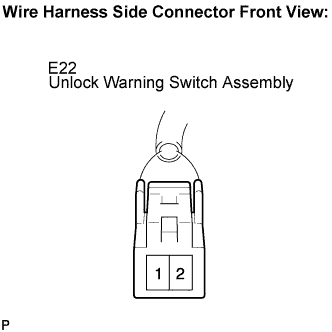
| 4.CHECK HARNESS AND CONNECTOR (UNLOCK WARNING SWITCH - BODY GROUND) |
Measure the resistance according to the value(s) in the table below.
- Standard resistance:
Tester Connection
| Condition
| Specified Condition
|
E22-2 - Body ground
| Always
| Below 1 Ω
|
| | REPAIR OR REPLACE HARNESS OR CONNECTOR |
|
|
| OK |
|
|
|
| PROCEED TO NEXT CIRCUIT INSPECTION SHOWN IN PROBLEM SYMPTOMS TABLE |
|