Body Electrical. Camry. Acv40 Gsv40
Door Lock. Camry. Acv40 Gsv40
Wireless Door Lock Control System (W/O Entry And Start System) -- Terminals Of Ecu |
| CHECK MAIN BODY ECU (INSTRUMENT PANEL J/B) |
Disconnect the main body ECU (instrument panel J/B) connectors.
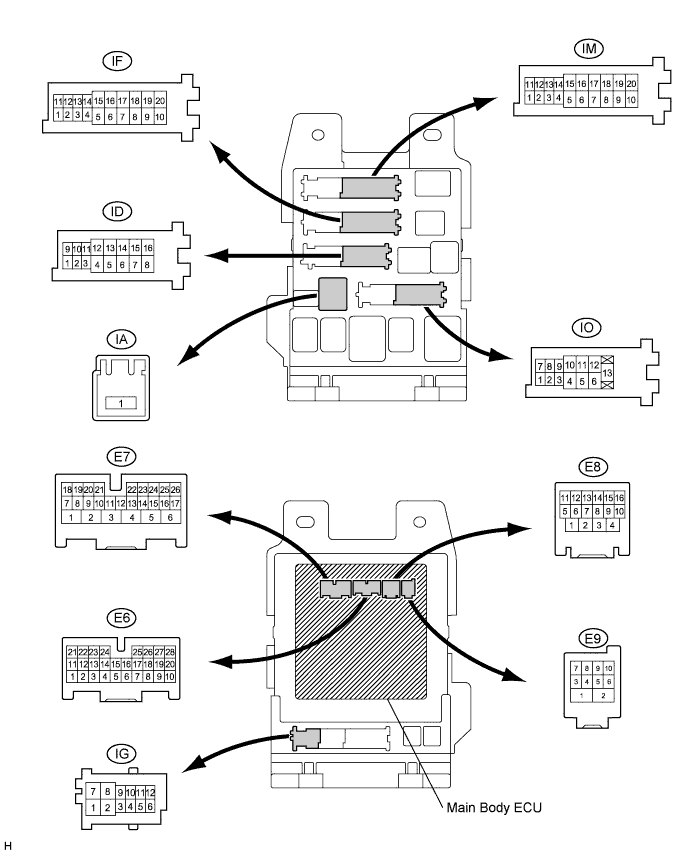
Measure the resistance and voltage between each terminal of the wire harness side connectors and body ground.
Symbols (Terminal No.) Wiring Color Terminal Description Condition Specified Condition RCTY (E6-5) - Body ground GR - Body ground Rear courtesy light switch RH input Rear door RH CLOSED (OFF) → OPEN (ON) 10 kΩ or higher → Below 1 Ω PCTY (E6-21) - Body ground Y *1 - Body ground Passenger side courtesy light switch input Passenger side door CLOSED (OFF) → OPEN (ON) 10 kΩ or higher → Below 1 Ω L *2 - Body ground LGCY (E6-25) - Body ground W - Body ground Luggage compartment door courtesy light switch input Luggage compartment door CLOSED (OFF) → OPEN (ON) 10 kΩ or higher → Below 1 Ω DCTY (E7-24) - Body ground L *1 - Body ground Driver side door courtesy light switch input Driver side door CLOSED (OFF) → OPEN (ON) 10 kΩ or higher → Below 1 Ω Y *2 - Body ground KSW (E9-5) - Body ground L - Body ground Unlock warning switch input No key in ignition key cylinder (OFF) → Key inserted (ON) 10 kΩ or higher → Below 1 Ω ACC (IA-1) - Body ground B - Body ground Ignition power supply (ACC signal) Ignition switch on (ACC) → off 10 to 14 V → Below 1 V IG (IA-1) - Body ground B - Body ground Ignition power supply (IG signal) Ignition switch on (IG) → off 10 to 14 V → Below 1 V ALTB (ID-15) - Body ground W - Body ground +B (power system alternator system) power supply Always 10 to 14 V GND1 (IF-10) - Body ground W-B - Body ground Ground Always Below 1 Ω BECU (ID-10) - Body ground O - Body ground +B power supply Always 10 to 14 V GND2 (IM-9) - Body ground W-B - Body ground Ground Always Below 1 Ω LCTY (IO-7) - Body ground LG - Body ground Rear courtesy light switch LH input Rear door LH CLOSED (OFF) → OPEN (ON) 10 kΩ or higher → Below 1 Ω - HINT:
- *1: LHD
- *2: RHD
Reconnect the main body ECU (instrument panel J/B) connectors.
Measure the voltage between each terminal of the wire harness side connectors and body ground.
Symbols (Terminal No.) Wiring Color Terminal Description Condition Specified Condition TR+ (E7-1) - Body ground B - Body ground Luggage compartment door opener motor input Luggage compartment door CLOSED (LOCKED) → OPEN (UNLOCKED) Below 1 V → 10 to 14 V*3 HAZ (E8-4) - Body ground W - Body ground Turn signal flasher relay signal Any transmitter switch is pressed → not pressed Below 1 V → 10 to 14 V*4 - HINT:
- *3: When operating the motor.
- *4: When operating the answer back function.