Power Door Lock Control System Door Control Switch Circuit
DESCRIPTION
WIRING DIAGRAM
INSPECTION PROCEDURE
READ VALUE USING INTELLIGENT TESTER
INSPECT DOOR CONTROL SWITCH ASSEMBLY
CHECK WIRE HARNESS (DOOR CONTROL SWITCH - MAIN BODY ECU (INSTRUMENT PANEL J/B))
POWER DOOR LOCK CONTROL SYSTEM - Door Control Switch Circuit |
DESCRIPTION
- for LHD
The main body ECU (instrument panel J/B) receives switch signals from the power window regulator master switch assembly via LIN communication and activates the door lock motor on each door according to these signals. - for RHD
The main body ECU (instrument panel J/B) receives switch signals from the power window regulator master switch assembly and activates the door lock motor on each door according to these signals.
WIRING DIAGRAM
INSPECTION PROCEDURE
- NOTICE:
- The power door lock control system for LHD uses the LIN communication system. First, confirm that there is no malfunction in the LIN communication system. Refer to the How to Proceed with Troubleshooting procedure (Link).
| 1.READ VALUE USING INTELLIGENT TESTER |
Connect the intelligent tester to the DLC3.
Turn the ignition switch on (IG).
Turn the intelligent tester on.
for LHD:
Enter the following menus: Body / Master Switch / Data List.
Read the Data List according to the display on the intelligent tester.
Master Switch:Tester Display
| Measurement Item / Range
| Normal Condition
| Diagnostic Note
|
Door Lock Switch Status
| Door control switch lock signal/ON or OFF
| ON: Door control switch is pushed to lock position
OFF: Door control switch is not pushed to lock position
| -
|
Door Unlock Switch Status
| Door control switch unlock signal/ON or OFF
| ON: Door control switch is pushed to unlock position
OFF: Door control switch is not pushed to unlock position
| -
|
- OK:
- The display is as specified in the normal condition column.
for RHD:
Enter the following menus: Body / Main Body / Data List.
Read the Data List according to the display on the intelligent tester.
Main Body:Tester Display
| Measurement Item / Range
| Normal Condition
| Diagnostic Note
|
Door Lock SW-Lock
| Door control switch lock signal/ON or OFF
| ON: Door control switch is pushed to lock position
OFF: Door control switch is not pushed to lock position
| -
|
Door Lock SW-Unlock
| Door control switch unlock signal/ON or OFF
| ON: Door control switch is pushed to unlock position
OFF: Door control switch is not pushed to unlock position
| -
|
- OK:
- The display is as specified in the normal condition column.
- Result:
Result
| Proceed to
|
OK
| A
|
NG (for LHD)
| B
|
NG (for RHD)
| C
|
| | REPLACE POWER WINDOW REGULATOR MASTER SWITCH ASSEMBLY |
|
|
| |
|
| A |
|
|
|
| PROCEED TO NEXT CIRCUIT INSPECTION SHOWN IN PROBLEM SYMPTOMS TABLE |
|
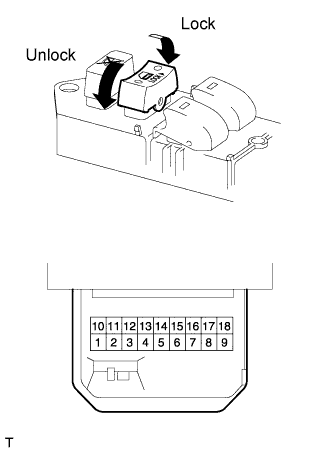
| 2.INSPECT DOOR CONTROL SWITCH ASSEMBLY |
Remove the master switch.
Measure the resistance of the door control switch.
- Standard resistance:
Tester Connection
| Switch Condition
| Specified Condition
|
2 - 9
| Lock
| Below 1 Ω
|
2 - 9
| OFF (Free)
| 10 kΩ or higher
|
8 - 9
| Unlock
| Below 1 Ω
|
8 - 9
| OFF (Free)
| 10 kΩ or higher
|
| | REPLACE POWER WINDOW REGULATOR MASTER SWITCH ASSEMBLY |
|
|
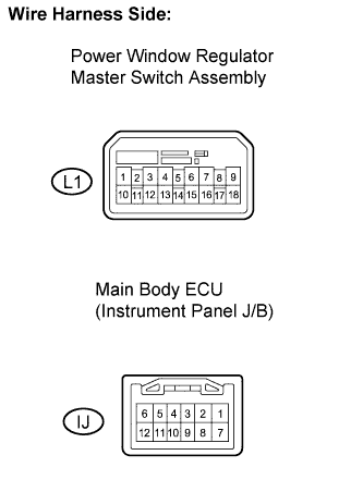
| 3.CHECK WIRE HARNESS (DOOR CONTROL SWITCH - MAIN BODY ECU (INSTRUMENT PANEL J/B)) |
Disconnect the door control switch connector.
Disconnect the ECU (instrument panel J/B) connector.
Measure the resistance according to the value(s) in the table below.
- Standard resistance:
Tester Connection
| Condition
| Specified Condition
|
L1-2 - IJ-3
| Always
| Below 1 Ω
|
L1-8 - IJ-4
| Always
| Below 1 Ω
|
L1-9 - Body ground
| Always
| Below 1 Ω
|
IJ-3 - Body ground
| Always
| 10 kΩ or higher
|
IJ-4 - Body ground
| Always
| 10 kΩ or higher
|
| | REPAIR OR REPLACE HARNESS OR CONNECTOR |
|
|
| OK |
|
|
|
| PROCEED TO NEXT CIRCUIT INSPECTION SHOWN IN PROBLEM SYMPTOMS TABLE |
|