Body Electrical. Camry. Acv40 Gsv40
Wiper And Washer. Camry. Acv40 Gsv40
Wiper And Washer System -- Terminals Of Ecu |
| CHECK WINDSHIELD WIPER RELAY ASSEMBLY (AUTO WIPER RELAY) |
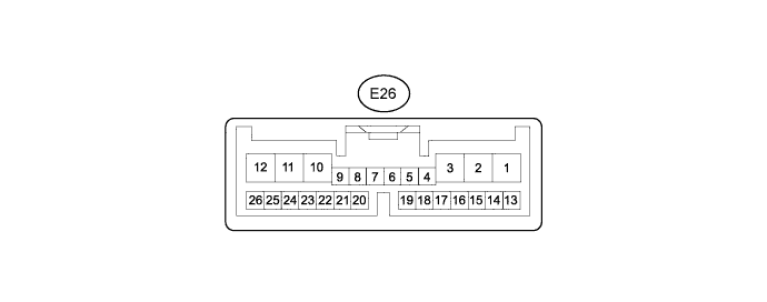
Disconnect the E26 relay connector.
Measure the voltage and resistance of the wire harness side connector.
If the result is not as specified, there may be a malfunction on the wire harness side.Symbols (Terminal No.) Wiring Color Terminal Description Condition Specified Condition W (E26-4) - Body ground GR - Body ground Front washer switch circuit Front washer switch is ON Below 1 Ω Front washer switch is OFF 10 kΩ or higher IG (E26-12) - Body ground L - Body ground IG signal circuit Ignition switch ON 10 to 14 V Ignition switch OFF Below 1 V WIG (E26-23) - Body ground B - Body ground WIG signal circuit Ignition switch ON 10 to 14 V Ignition switch OFF Below 1 V E (E26-26) - Body ground W-B - Body ground Body ground Always Below 1 Ω Reconnect the E26 relay connector.
Measure the voltage of the connector.
If the result is not as specified, the relay may have a malfunction.Symbols (Terminal No.) Wiring Color Terminal Description Condition Specified Condition +2S (E26-1) - Body ground P - Body ground Front wiper LO speed signal circuit Ignition switch ON,
front wiper switch LO10 to 14 V Ignition switch ON,
front wiper switch except LOBelow 1 V +1 (E26-2) - Body ground R - Body ground Front wiper motor LO speed signal circuit Front wiper motor is in LO operation 10 to 14 V Front wiper motor is OFF Below 1 V +2 (E26-3) - Body ground V - Body ground Front wiper motor HI speed signal circuit Front wiper motor is in HI operation 10 to 14 V Front wiper motor is OFF Below 1 V W (E26-4) - Body ground GR - Body ground Front washer motor circuit Front washer switch is ON Below 1 V Front washer switch is OFF 10 to 14 V +SM (E26-10) - Body ground Y- Body ground Front wiper motor operation signal Front wiper motor is in LO or HI operation 10 to 14 V Front wiper motor is OFF Below 1 V C1 (E26-17) - C0 (E26-16) P - R IG signal circuit Ignition switch ON 10 to 14 V Ignition switch OFF Below 1 V
| CHECK HEADLIGHT CLEANER CONTROL RELAY |

Disconnect the A39 relay connector.
Measure the voltage and resistance of the wire harness side connector.
If the result is not as specified, there may be a malfunction on the wire harness side.Symbols (Terminal No.) Wiring Color Terminal Description Condition Specified Condition IG (A39-3) - Body ground GR - Body ground IG signal circuit Ignition switch ON 10 to 14 V Ignition switch OFF Below 1 V E (A39-4) - Body ground BR - Body ground Body ground Always Below 1 Ω Reconnect the A39 relay connector.
Measure the voltage of the connector.
If the result is not as specified, the relay may have a malfunction.Symbols (Terminal No.) Wiring Color Terminal Description Condition Specified Condition HDLO (A39-1) - Body ground P - Body ground Headlight LO signal Headlight control switch LO Below 1 V Headlight control switch except LO 10 to 14 V H (A39-2) - Body ground Y - Body ground Headlight cleaner switch signal Headlight cleaner switch ON,
headlight control switch LOBelow 1 V Headlight cleaner switch ON,
headlight control switch except LO10 to 14 V FRWA (A39-5) - Body ground L - Body ground Front washer motor operation signal Front washer switch is ON Below 1 V Front washer switch is OFF 10 to 14 V PB (A39-6) - Body ground W - Body ground Headlight cleaner motor signal Headlight cleaner switch ON,
headlight control switch except LO10 to 14 V Headlight cleaner switch ON,
headlight control switch LOBelow 1 V