Lighting System Height Control Sensor Circuit
DESCRIPTION
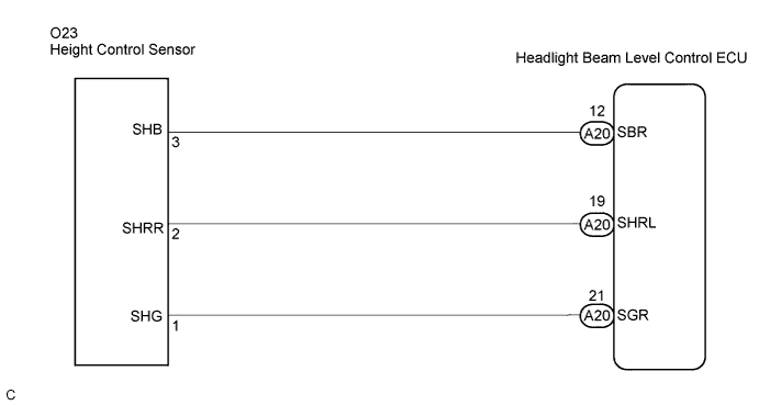
WIRING DIAGRAM
INSPECTION PROCEDURE
INSPECT REAR HEIGHT CONTROL SENSOR SUB-ASSEMBLY
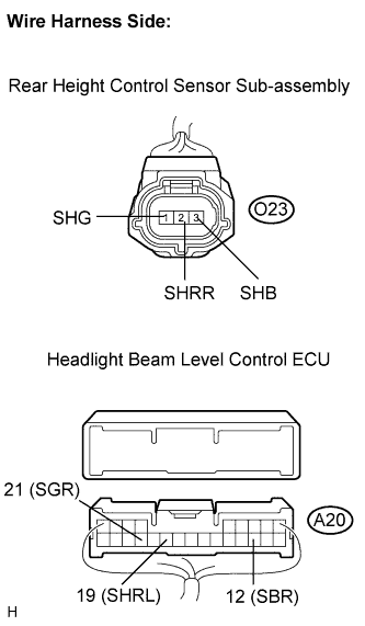
CHECK HARNESS AND CONNECTOR (ECU - REAR HEIGHT CONTROL SENSOR SUB-ASSEMBLY)
LIGHTING SYSTEM - Height Control Sensor Circuit |
DESCRIPTION
The headlight beam level control ECU receives a signal from the rear height control sensor sub-assembly to detect the vehicle height.
WIRING DIAGRAM
INSPECTION PROCEDURE
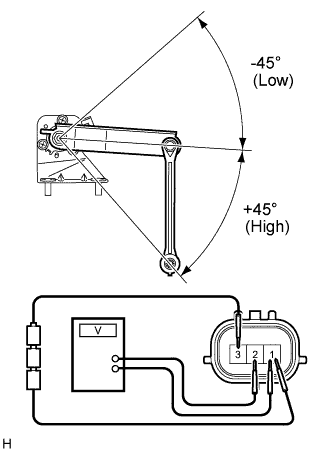
| 1.INSPECT REAR HEIGHT CONTROL SENSOR SUB-ASSEMBLY |
Connect 3 dry cell batteries (1.5 V) in series.
Remove the rear height control sensor sub-assembly.
Connect the positive (+) lead from the battery to terminal 3, and the negative (-) lead from the battery to terminal 1.
Measure the voltage between terminals 2 and 1 while slowly moving the link up and down.
- Standard voltage:
Tester Connection
| Condition
| Specified Condition
|
2 (SHRR) - 1 (SHG)
| +45° (High)
| Approx. 4.05 V
|
0° (Normal)
| Approx. 2.25 V
|
-45° (Low)
| Approx. 0.45 V
|
| | REPLACE REAR HEIGHT CONTROL SENSOR SUB-ASSEMBLY |
|
|
| 2.CHECK HARNESS AND CONNECTOR (ECU - REAR HEIGHT CONTROL SENSOR SUB-ASSEMBLY) |
Disconnect the O23 rear height control sensor sub-assembly connector.
Disconnect the A20 headlight beam level control ECU connector.
Measure the resistance according to the value(s) in the table below.
- Standard resistance:
Tester Connection
| Condition
| Specified Condition
|
A20-12 (SBR) - O23-3 (SHB)
| Always
| Below 1 Ω
|
A20-19 (SHRL) - O23-2 (SHRR)
| Always
| Below 1 Ω
|
A20-21 (SGR) - O23-1 (SHG)
| Always
| Below 1 Ω
|
A20-12 (SBR) - Body ground
| Always
| 10 kΩ or higher
|
A20-19 (SHRL) - Body ground
| Always
| 10 kΩ or higher
|
A20-21 (SGR) - Body ground
| Always
| 10 kΩ or higher
|
| | REPAIR OR REPLACE HARNESS OR CONNECTOR |
|
|
| OK |
|
|
|
| PROCEED TO NEXT CIRCUIT INSPECTION SHOWN IN PROBLEM SYMPTOMS TABLE |
|