Lighting System Light Control Switch Circuit
DESCRIPTION
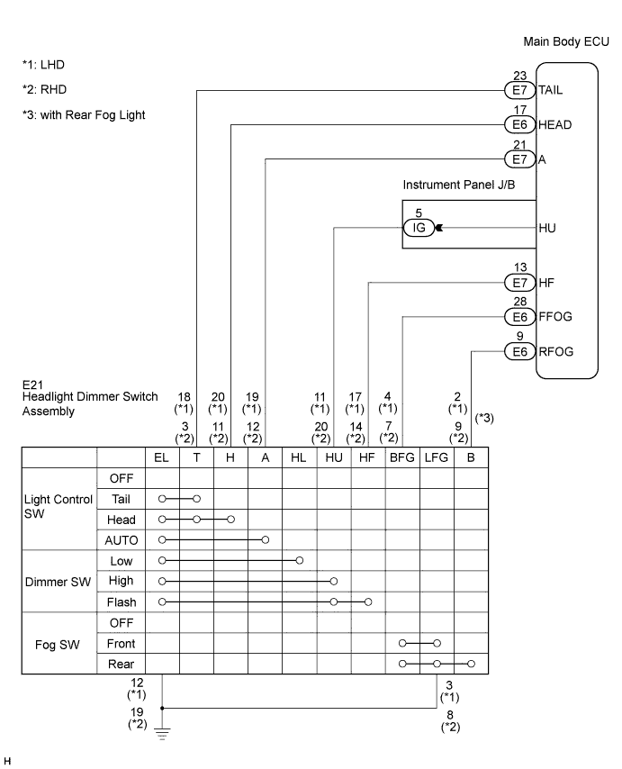
WIRING DIAGRAM
INSPECTION PROCEDURE
READ VALUE USING INTELLIGENT TESTER
INSPECT HEADLIGHT DIMMER SWITCH ASSEMBLY
CHECK VEHICLE CONDITION
CHECK HARNESS AND CONNECTOR (SWITCH - INSTRUMENT PANEL J/B AND BODY GROUND)
CHECK HARNESS AND CONNECTOR (SWITCH - INSTRUMENT PANEL J/B AND BODY GROUND)
LIGHTING SYSTEM - Light Control Switch Circuit |
DESCRIPTION
The main body ECU receives the following switch information.- Light control switch position is OFF, TAIL, HEAD, or AUTO
- Dimmer switch position is HIGH, LOW, or HIGH FLASH (PASS)
- Fog light switch position is OFF, FRONT, or REAR
WIRING DIAGRAM
INSPECTION PROCEDURE
| 1.READ VALUE USING INTELLIGENT TESTER |
Connect the intelligent tester to the DLC3.
Turn the ignition switch to the ON position and turn the intelligent tester main switch on.
Select the items below in the DATA LIST, and read the displays on the intelligent tester.
Main Body (Main Body ECU):Item
| Measurement/
Display (Range)
| Normal Condition
| Diagnostic Note
|
Dimmer Hi SW
| Dimmer switch HIGH signal / ON or OFF
| ON: Dimmer switch in HIGH
OFF: Dimmer switch in LOW
| -
|
Passing Light SW
| Dimmer switch FLASH signal / ON or OFF
| ON: Dimmer switch in HIGH FLASH (PASS)
OFF: Dimmer switch not in HIGH FLASH (PASS)
| -
|
Front Fog Light SW
| Front fog light switch signal / ON or OFF
| ON: Front fog light switch ON
OFF: Front fog light switch OFF
| -
|
Rear Fog Light SW
| Rear fog light switch signal / ON or OFF
| ON: Rear fog light switch ON
OFF: Rear fog light switch OFF
| -
|
Light Auto SW
| Light control switch AUTO signal / ON or OFF
| ON: Light control switch in AUTO
OFF: Light control switch not in AUTO
| -
|
Headlight SW
| Light control switch HEAD signal / ON or OFF
| ON: Light control switch in HEAD
OFF: Light control switch not in HEAD
| -
|
Taillight SW
| Light control switch TAIL signal / ON or OFF
| ON: Light control switch in TAIL or HEAD
OFF: Light control switch in neither TAIL nor HEAD
| -
|
- OK:
- Normal conditions listed above are displayed.
| | PROCEED TO NEXT CIRCUIT INSPECTION SHOWN IN PROBLEM SYMPTOMS TABLE |
|
|
| 2.INSPECT HEADLIGHT DIMMER SWITCH ASSEMBLY |
Inspect the headlight dimmer switch assembly (CAMRY_ACV40 RM0000014E3006X.html).
| | REPLACE HEADLIGHT DIMMER SWITCH ASSEMBLY |
|
|
| 3.CHECK VEHICLE CONDITION |
- Result:
Vehicle Condition
| Proceed to
|
LHD
| A
|
RHD
| B
|
| 4.CHECK HARNESS AND CONNECTOR (SWITCH - INSTRUMENT PANEL J/B AND BODY GROUND) |
Disconnect the E21 headlight dimmer switch assembly connector.
Disconnect the E6 and E7 main body ECU connectors.
Disconnect the IG instrument panel J/B connector.
Measure the resistance according to the value(s) in the table below.
- Standard resistance:
Tester Connection
| Condition
| Specified Condition
|
E21-2 (B) - E6-9 (RFOG)
| Always
| Below 1 Ω
|
E21-4 (BFG) - E6-28 (FFOG)
| Always
| Below 1 Ω
|
E21-11 (HU) - IG-5 (HU)
| Always
| Below 1 Ω
|
E21-17 (HF) - E7-13 (HF)
| Always
| Below 1 Ω
|
E21-18 (T) - E7-23 (TAIL)
| Always
| Below 1 Ω
|
E21-19 (A) - E7-21 (A)
| Always
| Below 1 Ω
|
E21-20 (H) - E6-17 (HEAD)
| Always
| Below 1 Ω
|
E21-2 (B) - Body ground
| Always
| 10 kΩ higher
|
E21-3 (LFG) - Body ground
| Always
| 10 kΩ higher
|
E21-4 (BFG) - Body ground
| Always
| 10 kΩ higher
|
E21-11 (HU) - Body ground
| Always
| 10 kΩ higher
|
E21-17 (HF) - Body ground
| Always
| 10 kΩ higher
|
E21-18 (T) - Body ground
| Always
| 10 kΩ higher
|
E21-19 (A) - Body ground
| Always
| 10 kΩ higher
|
E21-20 (H) - Body ground
| Always
| 10 kΩ higher
|
E21-12 (EL) - Body ground
| Always
| Below 1 Ω
|
E21-3 (LFG) - Body ground
| Always
| Below 1 Ω
|
| | REPAIR OR REPLACE HARNESS OR CONNECTOR |
|
|
| OK |
|
|
|
| REPLACE INSTRUMENT PANEL JUNCTION BLOCK ASSEMBLY |
|
| 5.CHECK HARNESS AND CONNECTOR (SWITCH - INSTRUMENT PANEL J/B AND BODY GROUND) |
Disconnect the E21 headlight dimmer switch assembly connector.
Disconnect the E6 and E7 main body ECU connectors.
Disconnect the IG instrument panel J/B connector.
Measure the resistance according to the value(s) in the table below.
- Standard resistance:
Tester Connection
| Condition
| Specified Condition
|
E21-3 (T) - E7-23 (TAIL)
| Always
| Below 1 Ω
|
E21-7 (BFG) - E6-28 (FFOG)
| Always
| Below 1 Ω
|
E21-9 (B) - E6-9 (RFOG)
| Always
| Below 1 Ω
|
E21-11 (H) - E6-17 (HEAD)
| Always
| Below 1 Ω
|
E21-12 (A) - E7-21 (A)
| Always
| Below 1 Ω
|
E21-14 (HF) - E7-13 (HF)
| Always
| Below 1 Ω
|
E21-20 (HU) - IG-5 (HU)
| Always
| Below 1 Ω
|
E21-3 (T) - Body ground
| Always
| 10 kΩ higher
|
E21-7 (BFG) - Body ground
| Always
| 10 kΩ higher
|
E21-9 (B) - Body ground
| Always
| 10 kΩ higher
|
E21-11 (H) - Body ground
| Always
| 10 kΩ higher
|
E21-12 (A) - Body ground
| Always
| 10 kΩ higher
|
E21-14 (HF) - Body ground
| Always
| 10 kΩ higher
|
E21-20 (HU) - Body ground
| Always
| 10 kΩ higher
|
E21-19 (EL) - Body ground
| Always
| Below 1 Ω
|
E21-8 (LFG) - Body ground
| Always
| Below 1 Ω
|
| | REPAIR OR REPLACE HARNESS OR CONNECTOR |
|
|
| OK |
|
|
|
| REPLACE INSTRUMENT PANEL JUNCTION BLOCK ASSEMBLY |
|