Lighting System Ignition Switch Circuit
DESCRIPTION
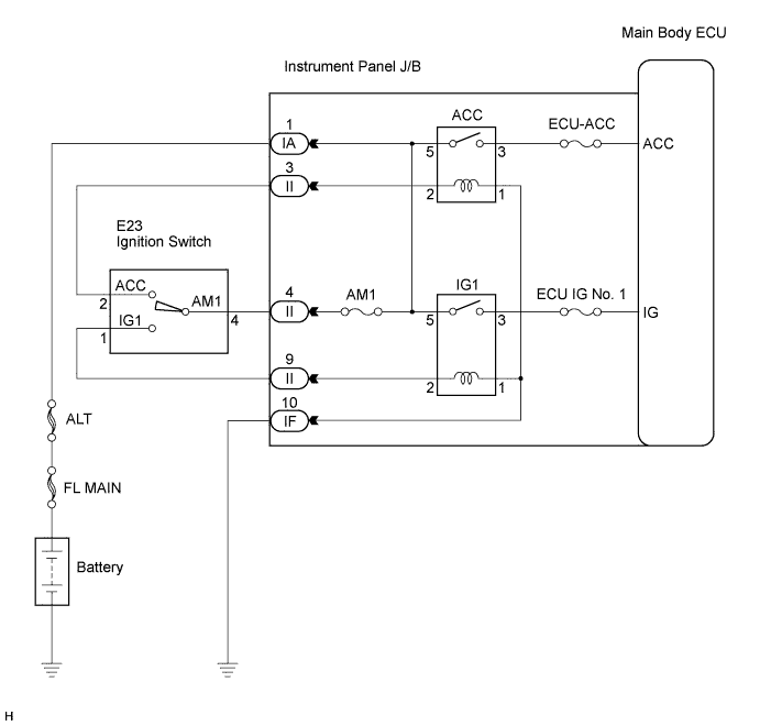
WIRING DIAGRAM
INSPECTION PROCEDURE
READ VALUE USING INTELLIGENT TESTER
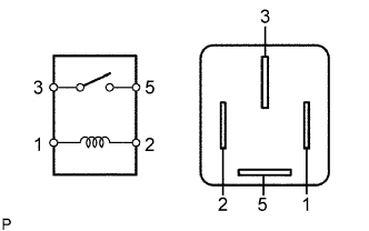
INSPECT ACC RELAY
INSPECT NO. 1 IGNITION RELAY
CHECK HARNESS AND CONNECTOR (INSTRUMENT PANEL J/B ASSEMBLY - BATTERY AND GROUND)
CHECK HARNESS AND CONNECTOR (INSTRUMENT PANEL J/B ASSEMBLY - IGNITION SWITCH)
INSPECT IGNITION SWITCH
LIGHTING SYSTEM - Ignition Switch Circuit |
DESCRIPTION
This circuit detects the state of the ignition switch, and sends it to the main body ECU.
WIRING DIAGRAM
INSPECTION PROCEDURE
| 1.READ VALUE USING INTELLIGENT TESTER |
Connect the intelligent tester to the DLC3.
Turn the ignition switch to the ON position and turn the intelligent tester main switch on.
Select the items below in the DATA LIST, and read the display on the intelligent tester.
Main Body (Main Body ECU):Item
| Measurement Item / Display (Range)
| Normal Condition
| Diagnostic Note
|
ACC SW
| Ignition switch ACC signal / ON or OFF
| ON: Ignition switch ON or ACC
OFF: Ignition switch off
| -
|
IG SW
| Ignition switch IG signal / ON or OFF
| ON: Ignition switch ON or ACC
OFF: Ignition switch off
| -
|
- OK:
- Normal conditions listed above are displayed.
| | PROCEED TO NEXT CIRCUIT INSPECTION SHOWN IN PROBLEM SYMPTOMS TABLE |
|
|
Remove the ACC relay from the instrument panel J/B assembly.
Measure the resistance according to the value(s) in the table below.
- Standard resistance:
Tester Connection
| Specified Condition
|
3 - 5
| 10 kΩ or higher
|
Below 1 Ω (When battery voltage is applied to terminals 1 and 2)
|
| 3.INSPECT NO. 1 IGNITION RELAY |
Remove the No. 1 ignition relay from the instrument panel J/B assembly.
Measure the resistance according to the value(s) in the table below.
- Standard resistance:
Tester Connection
| Specified Condition
|
3 - 5
| 10 kΩ or higher
|
Below 1 Ω (When battery voltage is applied to terminals 1 and 2)
|
| | REPLACE NO. 1 IGNITION RELAY |
|
|
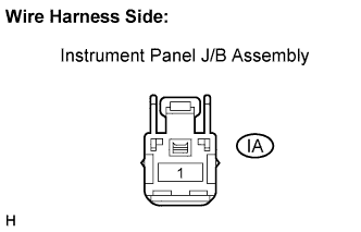
| 4.CHECK HARNESS AND CONNECTOR (INSTRUMENT PANEL J/B ASSEMBLY - BATTERY AND GROUND) |
Disconnect the IA instrument panel J/B assembly connector.
Measure the voltage according to the value(s) in the table below.
- Standard voltage:
Tester Connection
| Condition
| Specified Condition
|
IA-1 - Body ground
| Always
| 10 to 14 V
|
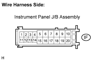
Disconnect the IF instrument panel J/B assembly connector.
Measure the resistance according to the value(s) in the table below.
- Standard resistance:
Tester Connection
| Condition
| Specified Condition
|
IF-10 - Body ground
| Always
| Below 1 Ω
|
| | REPAIR OR REPLACE HARNESS OR CONNECTOR |
|
|
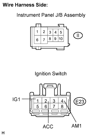
| 5.CHECK HARNESS AND CONNECTOR (INSTRUMENT PANEL J/B ASSEMBLY - IGNITION SWITCH) |
Disconnect the E23 ignition switch connector.
Disconnect the II instrument panel J/B assembly connector.
Measure the resistance according to the value(s) in the table below.
- Standard resistance:
Tester Connection
| Condition
| Specified Condition
|
II-3 - E23-2 (ACC)
| Always
| Below 1 Ω
|
II-4 - E23-4 (AM1)
| Always
| Below 1 Ω
|
II-9 - E23-1 (IG1)
| Always
| Below 1 Ω
|
II-3 - Body ground
| Always
| 10 kΩ or higher
|
II-4 - Body ground
| Always
| 10 kΩ or higher
|
II-9 - Body ground
| Always
| 10 kΩ or higher
|
| | REPAIR OR REPLACE HARNESS OR CONNECTOR |
|
|
| 6.INSPECT IGNITION SWITCH |
Inspect the ignition switch (CAMRY_ACV40 RM0000026VF003X.html)
- OK:
- Ignition switch is normal.
| OK |
|
|
|
| REPLACE INSTRUMENT PANEL J/B ASSEMBLY |
|