Engine Immobiliser System (W/O Entry And Start System) Door Courtesy Switch Circuit
DESCRIPTION
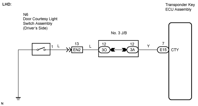
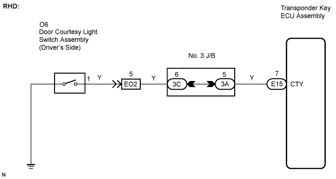
WIRING DIAGRAM
INSPECTION PROCEDURE
CHECK HARNESS AND CONNECTOR (FRONT DOOR COURTESY LIGHT SWITCH CIRCUIT)
INSPECT FRONT DOOR COURTESY LIGHT SWITCH ASSEMBLY
ENGINE IMMOBILISER SYSTEM (w/o Entry and Start System) - Door Courtesy Switch Circuit |
DESCRIPTION
When an additional transponder key is registered, the transponder key ECU assembly detects the front door courtesy light switch open/close condition, and enters the key registration mode.
WIRING DIAGRAM
INSPECTION PROCEDURE
- NOTICE:
- If the transponder key ECU assembly is replaced, register the key and ECU communication ID.
| 1.CHECK HARNESS AND CONNECTOR (FRONT DOOR COURTESY LIGHT SWITCH CIRCUIT) |
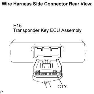
Disconnect the E15 ECU connector.
Measure the resistance according to the value(s) in the table below.
- Standard resistance:
Tester Connection
| Condition
| Specified Condition
|
E15-7 (CTY) - Body ground
| Courtesy switch pushed
(Door closed)
| 10 kΩ or higher
|
Courtesy switch free
(Door open)
| Below 1 Ω
|
| | PROCEED TO NEXT CIRCUIT INSPECTION SHOWN IN PROBLEM SYMPTOMS TABLE |
|
|
| 2.INSPECT FRONT DOOR COURTESY LIGHT SWITCH ASSEMBLY |
Remove the driver side front door courtesy light switch (CAMRY_ACV40 RM000001WIV005X.html).
Measure the resistance according to the value(s) in the table below.
- Standard resistance:
Tester Connection
| Condition
| Specified Condition
|
1 - Switch body
| Courtesy switch pushed
(Door closed)
| 10 kΩ or higher
|
Courtesy switch free
(Door open)
| Below 1 Ω
|
| | REPLACE FRONT DOOR COURTESY LIGHT SWITCH ASSEMBLY |
|
|
| OK |
|
|
|
| REPAIR OR REPLACE HARNESS OR CONNECTOR (TRANSPONDER KEY ECU - FRONT DOOR COURTESY LIGHT SWITCH) |
|