Theft Deterrent System (W/ Entry And Start System) Ecu Power Source Circuit
DESCRIPTION
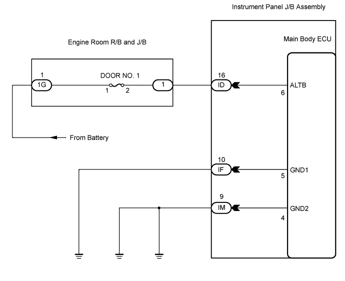
WIRING DIAGRAM
INSPECTION PROCEDURE
CHECK INSTRUMENT PANEL JUNCTION BLOCK ASSEMBLY (MAIN BODY ECU) (POWER SOURCE)
CHECK HARNESS AND CONNECTOR (INSTRUMENT PANEL J/B - BODY GROUND)
THEFT DETERRENT SYSTEM (w/ Entry and Start System) - ECU Power Source Circuit |
DESCRIPTION
This circuit provides power for main body ECU operation.
WIRING DIAGRAM
INSPECTION PROCEDURE
| 1.CHECK INSTRUMENT PANEL JUNCTION BLOCK ASSEMBLY (MAIN BODY ECU) (POWER SOURCE) |
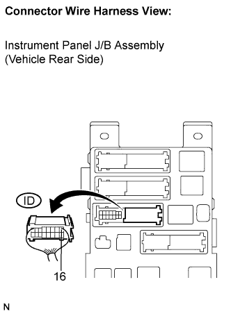
Disconnect the ID J/B connector.
Measure the voltage according to the value(s) in the table below.
- Standard voltage:
Tester Connection
| Condition
| Specified Condition
|
ID-16 - Body ground
| Always
| 11 to 14 V
|
| | REPAIR OR REPLACE HARNESS OR CONNECTOR |
|
|
| 2.CHECK HARNESS AND CONNECTOR (INSTRUMENT PANEL J/B - BODY GROUND) |
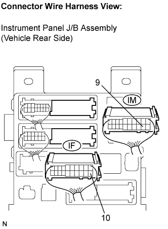
Disconnect the IF and IM J/B connectors.
Measure the resistance according to the value(s) in the table below.
- Standard resistance:
Symbol (Tester Connection)
| Condition
| Specified Condition
|
IF-10 - Body ground
| Always
| Below 1 Ω
|
IM-9 - Body ground
| Always
|
| | REPAIR OR REPLACE HARNESS OR CONNECTOR |
|
|