REMOVE TURN SIGNAL SWITCH ASSEMBLY WITH SPIRAL CABLE SUB-ASSEMBLY
REMOVE SHIFT LEVER KNOB SUB-ASSEMBLY (for Automatic Transaxle)
REMOVE FLOOR SHIFT POSITION INDICATOR HOUSING SUB-ASSEMBLY (for Automatic Transaxle)
REMOVE UPPER CONSOLE REAR PANEL SUB-ASSEMBLY (for Automatic Transaxle)
REMOVE UPPER CONSOLE REAR PANEL SUB-ASSEMBLY (for Manual Transaxle)
REMOVE LOWER INSTRUMENT CLUSTER FINISH PANEL CENTER SUB-ASSEMBLY
REMOVE RADIO TUNER OPENING COVER WITH HEATER CONTROL PANEL ASSEMBLY (w/o Radio Receiver)
REMOVE RADIO RECEIVER WITH HEATER CONTROL PANEL ASSEMBLY (w/ Radio Receiver)
Blower Unit -- Removal |
| 1. RECOVER REFRIGERANT FROM REFRIGERATION SYSTEM |
Start up the engine.
Turn the A/C switch on.
Operate the cooler compressor at an engine speed of approximately 1,000 rpm for 5 to 6 minutes to circulate the refrigerant. This causes most of the compressor oil from the various components of the A/C system to collect in the A/C compressor.
Stop the engine.
Recover the refrigerant from the A/C system using a refrigerant recovery unit.
| 2. ALIGN FRONT WHEELS FACING STRAIGHT AHEAD |
| 3. DISCONNECT BATTERY NEGATIVE TERMINAL |
- CAUTION:
- Wait for 90 seconds after disconnecting the terminal to prevent the airbag from deploying. (CAMRY_ACV40 RM000000KT1054X.html)
| 4. REMOVE FRONT WIPER ARM AND BLADE ASSEMBLY LH |
Remove the nut and the front wiper arm and blade assembly LH.
 |
| 5. REMOVE FRONT WIPER ARM AND BLADE ASSEMBLY RH |
Remove the nut and the front wiper arm and blade assembly RH.
 |
| 6. REMOVE FRONT FENDER TO COWL SIDE SEAL LH |
Disengage the claw and remove the front fender to cowl side seal LH.
 |
| 7. REMOVE FRONT FENDER TO COWL SIDE SEAL RH |
Disengage the claw and remove the front fender to cowl side seal RH.
 |
| 8. REMOVE COWL TOP VENTILATOR LOUVER SUB-ASSEMBLY |
Remove the 2 clips.
 |
Disengage the 4 claws and remove the cowl top ventilator louver sub-assembly.
| 9. REMOVE WINDSHIELD WIPER MOTOR AND LINK ASSEMBLY |
Disconnect the connector.
 |
Remove the 4 bolts and the windshield wiper motor and link assembly.
 |
| 10. REMOVE COWL TOP OUTER FRONT PANEL SUB-ASSEMBLY |
Disengage the clamp.
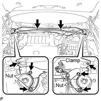 |
Remove the 4 nuts, the 4 bolts and the cowl top outer front panel sub-assembly.
| 11. DISCONNECT SUCTION PIPE SUB-ASSEMBLY |
Remove the bolt, and slide the hook connector.
 |
Disconnect the suction pipe sub-assembly.
Remove the O-ring from the suction hose sub-assembly.
- NOTICE:
- Seal the openings of the disconnected parts using vinyl tape to prevent entry of moisture and foreign matter.
| 12. DISCONNECT AIR CONDITIONING TUBE AND ACCESSORY |
Disconnect the air conditioning tube and accessory.
Remove the O-ring from the air conditioner tube and accessory.
- NOTICE:
- Seal the openings of the disconnected parts using vinyl tape to prevent entry of moisture and foreign matter.
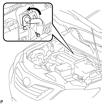
| 13. DISCONNECT HEATER WATER HOSE OUTLET |
Using pliers, grip the claws of the clip and slide the clip to disconnect the heater outlet water hose.
- NOTICE:
- Do not apply excessive force to the heater outlet water hose.
- Prepare a drain pan or cloth in case the coolant leaks.
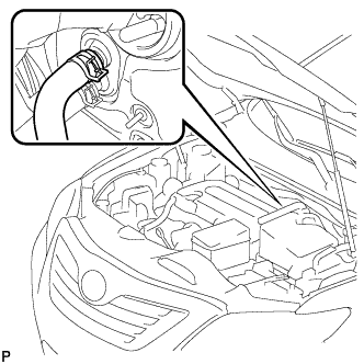 |
| 14. DISCONNECT HEATER WATER HOSE INLET |
Using pliers, grip the claws of the clip and slide the clip to disconnect the heater outlet water hose.
- NOTICE:
- Do not apply excessive force to the heater outlet water hose.
- Prepare a drain pan or cloth in case the coolant leaks.
|
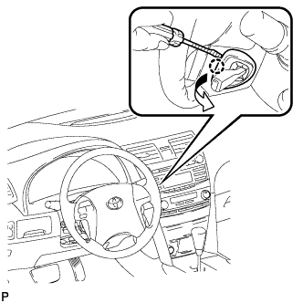
| 15. REMOVE LOWER NO. 3 STEERING WHEEL COVER |
Using a screwdriver, disengage the claw and remove the No. 3 lower steering wheel cover.
- HINT:
- Tape up the screwdriver tip before use.
 |
| 16. REMOVE LOWER NO. 2 STEERING WHEEL COVER |
Using a screwdriver, disengage the claw and remove the No. 2 lower steering wheel cover.
- HINT:
- Tape up the screwdriver tip before use.
 |
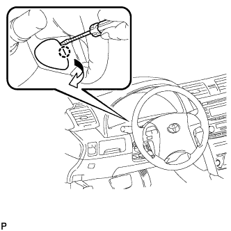
| 17. REMOVE STEERING PAD |
Using a "TORX" socket (T30), loosen the 2 "TORX" screws until the groove along the screw circumference catches on the screw case.
 |
Pull out the steering pad from the steering wheel assembly and support the steering pad with one hand.
- NOTICE:
- When removing the steering pad, do not pull the airbag wire harness.
 |
Disconnect the horn connector from the steering pad.
Disconnect the 2 airbag connectors and remove the steering pad.
- NOTICE:
- When handling the airbag connector, take care not to damage the airbag wire harness.
Remove the steering pad.
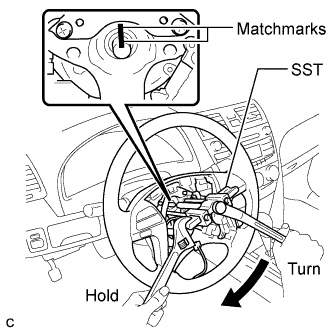
| 18. REMOVE STEERING WHEEL ASSEMBLY |
Remove the steering wheel assembly set nut.
Put matchmarks on the steering wheel assembly and the steering main shaft.
Disconnect the connectors from the spiral cable.
Using SST, remove the steering wheel assembly.
- SST
- 09950-50013(09951-05010,09952-05010,09953-05020,09954-05031)
 |
| 19. REMOVE FRONT DOOR SCUFF PLATE LH |
Disengage the 7 claws and 3 clips, and remove the front door scuff plate LH.
 |
| 20. REMOVE COWL SIDE TRIM SUB-ASSEMBLY LH |
Remove the cowl side trim clip.
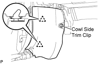 |
Disengage the 2 clips and remove the cowl side trim sub-assembly LH.
| 21. REMOVE LOWER INSTRUMENT PANEL FINISH PANEL LH |
Remove the bolt <A> and the screw <B>.
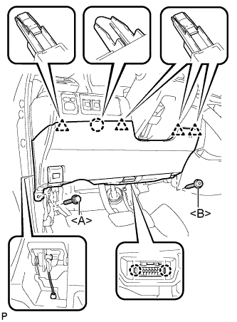 |
Disengage the 2 claws and the DLC3.
Disconnect the hood lock control cable assembly.
Disengage the claw and the 4 clips.
Remove the air hose, disconnect the connector, and then remove the lower instrument panel finish panel LH.
| 22. REMOVE STEERING COLUMN COVER |
Remove the 2 screws <D>.
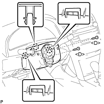 |
Disengage the 2 claws and remove the lower steering column cover.
Disengage the claw and remove the upper steering column cover.
| 23. REMOVE TURN SIGNAL SWITCH ASSEMBLY WITH SPIRAL CABLE SUB-ASSEMBLY |
Disconnect the connectors from the turn signal switch assembly with spiral cable sub-assembly.
Using pliers, grip the claws of the clip and remove the turn signal switch assembly with spiral cable sub-assembly.
 |
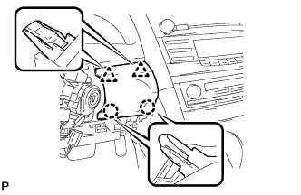
| 24. REMOVE NO. 1 INSTRUMENT PANEL SUB-ASSEMBLY |
Disengage the 3 claws and the 2 clips.
 |
Disconnect each connector and remove the instrument panel sub-assembly.
| 25. REMOVE LOWER INSTRUMENT PANEL FINISH PANEL |
Disengage the 2 claws and 2 clips, and then remove the lower instrument panel finish panel.
 |
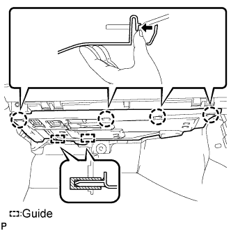
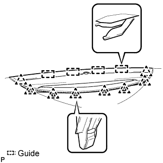
| 26. REMOVE INSTRUMENT CLUSTER FINISH PANEL NO.1 |
Remove the 2 clips.
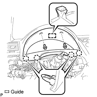 |
Disengage the guide and 4 claws and then remove the instrument cluster finish panel.
| 27. REMOVE COMBINATION METER ASSEMBLY |
Remove the 4 screws <E>.
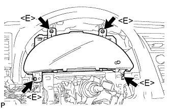 |
Disconnect each connector and remove the combination meter assembly.
| 28. REMOVE FRONT DOOR SCUFF PLATE RH |
- HINT:
- Use the same procedures for the RH side and the LH side.
| 29. REMOVE COWL SIDE TRIM SUB-ASSEMBLY RH |
Remove the cowl side trim clip.
|
Disengage the 2 clips and remove the cowl side trim sub-assembly LH.
| 30. REMOVE INSTRUMENT PANEL NO. 2 UNDER COVER SUB-ASSEMBLY |
Disengage the 4 claws.
 |
Disengage the 2 guides and remove the No. 2 under cover sub-assembly.
| 31. REMOVE LOWER INSTRUMENT PANEL SUB-ASSEMBLY |
Remove the bolt <A>.
Remove the 4 screws <B>.
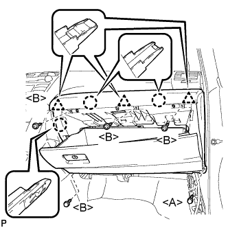 |
Disengage the 3 claws and 3 clips, and then remove the lower instrument panel sub-assembly.
| 32. REMOVE SHIFT LEVER KNOB SUB-ASSEMBLY (for Automatic Transaxle) |
Turn the shift lever knob counterclockwise and remove the shift lever knob sub-assembly.
 |
| 33. REMOVE SHIFT LEVER KNOB SUB-ASSEMBLY (for Manual Transaxle) |
Turn the shift lever knob counterclockwise and remove the shift lever knob sub-assembly.
 |
| 34. REMOVE NO. 1 INSTRUMENT CLUSTER FINISH PANEL GARNISH |
Disengage the 2 clips and remove the No. 1 instrument cluster finish panel garnish.
 |
| 35. REMOVE NO. 2 INSTRUMENT CLUSTER FINISH PANEL GARNISH |
Disengage the 2 clips and remove the No. 2 instrument cluster finish panel garnish.
 |
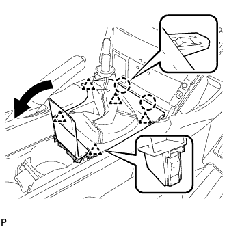
| 36. REMOVE FLOOR SHIFT POSITION INDICATOR HOUSING SUB-ASSEMBLY (for Automatic Transaxle) |
Disengage the 6 claws and the 3 clips, and then remove the floor shift position indicator housing sub-assembly.
 |
with Seat Heater System:
Disconnect each connector.
| 37. REMOVE UPPER CONSOLE PANEL (for Manual Transaxle) |
Open the lid of the upper console panel.
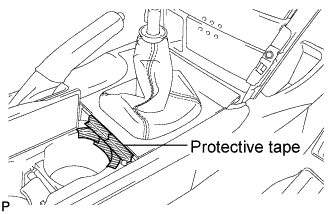 |
Apply protective tape to the area shown in the illustration.
Using a moulding remover, disengage the 2 claws and the 5 clips, and then remove the upper console panel as shown in the illustration.
 |
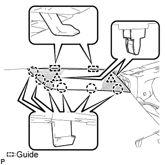
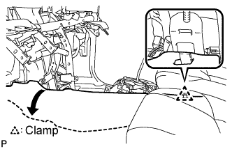
| 38. REMOVE UPPER CONSOLE REAR PANEL SUB-ASSEMBLY (for Automatic Transaxle) |
Disengage the 3 claws and the 5 clips.
 |
Disengage the clamp.
Disconnect the connector and remove the upper console rear panel sub-assembly.
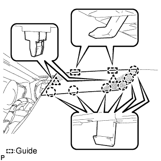
| 39. REMOVE UPPER CONSOLE REAR PANEL SUB-ASSEMBLY (for Manual Transaxle) |
Disengage the 3 claws and the 5 clips, and remove the upper console rear panel sub-assembly.
 |
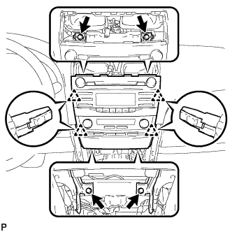
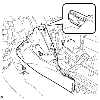
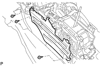
| 40. REMOVE LOWER INSTRUMENT CLUSTER FINISH PANEL CENTER SUB-ASSEMBLY |
Remove the 2 screws <F>.
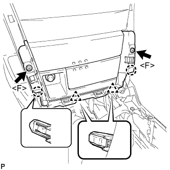 |
Disengage the 4 claws.
Disconnect each connector and remove the instrument cluster finish panel center sub-assembly.
- HINT:
- Set the shift lever in the D position.
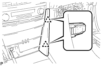
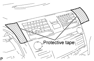
| 41. REMOVE INSTRUMENT PANEL NO. 2 REGISTER ASSEMBLY |
Apply protective tape to the areas shown in the illustration.
 |
Using a moulding remover, disengage the 3 clips.
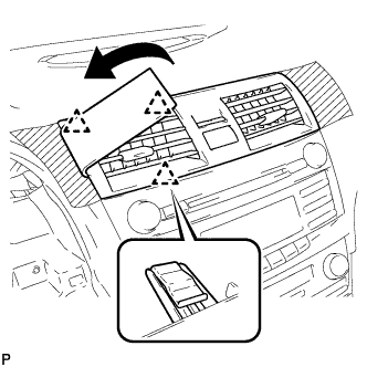 |
Using a moulding remover, disengage the 4 clips.
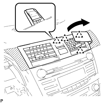 |
Disconnect the connector and remove the instrument panel No. 2 register assembly.
| 42. REMOVE RADIO TUNER OPENING COVER WITH HEATER CONTROL PANEL ASSEMBLY (w/o Radio Receiver) |
Remove the 4 bolts <N>.
 |
Disengage the 6 clips and remove the radio tuner opening cover with heater control panel assembly.
Disconnect the connector.
| 43. REMOVE RADIO RECEIVER WITH HEATER CONTROL PANEL ASSEMBLY (w/ Radio Receiver) |
Remove the 4 bolts.
 |
Pull the radio receiver with heater control panel assembly toward the rear of the vehicle and disengage the 4 clips.
Disconnect each connector and remove the radio receiver with heater control panel assembly.
| 44. REMOVE CONSOLE BOX POCKET |
Remove the console box pocket.
| 45. REMOVE CONSOLE BOX CARPET |
Remove the console box carpet.
 |
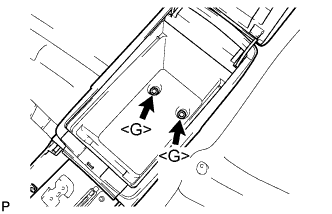
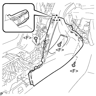
| 46. REMOVE CONSOLE BOX ASSEMBLY |
Remove the 2 screws <F>.
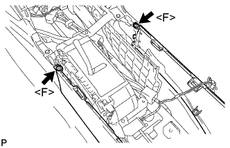 |
Remove the 2 bolts <G> and the console box assembly.
 |
| 47. REMOVE NO. 2 CONSOLE BOX INSERT FRONT |
Remove the 3 screws <F>.
 |
Disengage the clip and remove the No. 2 console box insert front.
| 48. REMOVE NO. 1 CONSOLE BOX INSERT FRONT |
Remove the 3 screws <F>.
 |
Disengage the clip and remove the No. 1 console box insert front.
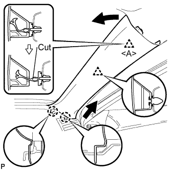
| 49. REMOVE FRONT PILLAR GARNISH LH |
Pull the upper part of the garnish toward the inside of the cabin and disengage the 2 clips.
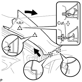 |
Cut off the clip <A>.
Disengage the 2 claws and remove the front pillar garnish LH.
Remove the clip <A> from the vehicle body.
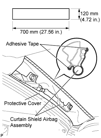
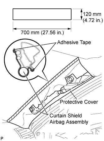
Protect the curtain shield airbag assembly.
Cover the airbag with a 700 mm (27.56 in.) x 120 mm (4.72 in.) cloth or piece of nylon and fix the ends of the cover with tape, as shown in the illustration.
- NOTICE:
- Cover the curtain shield airbag with a protective cover as soon as the front pillar garnish is removed.
 |
| 50. REMOVE INSTRUMENT PANEL NO. 1 REGISTER ASSEMBLY |
Disengage the 4 clips and remove the instrument panel No. 1 register assembly.
 |
| 51. REMOVE INSTRUMENT PANEL NO. 1 SPEAKER PANEL SUB-ASSEMBLY |
Disengage the 6 claws and the 2 clips.
 |
Disengage the 2 guides and remove the instrument panel No. 1 speaker panel sub-assembly.
| 52. REMOVE FRONT NO. 2 SPEAKER ASSEMBLY (for LH Side) |
Remove the 2 bolts and front No. 2 speaker assembly.
 |
Disconnect the connector.
| 53. REMOVE FRONT PILLAR GARNISH RH |
Pull the upper part of the garnish toward the inside of the cabin and disengage the 2 clips.
 |
Cut off the clip <A>.
Disengage the 2 claws and remove the front pillar garnish RH.
Remove the clip <A> from the vehicle body.
Protect the curtain shield airbag assembly.
Cover the airbag with a 700 mm (27.56 in.) x 120 mm (4.72 in.) cloth or piece of nylon and fix the ends of the cover with tape, as shown in the illustration.
- NOTICE:
- Cover the curtain shield airbag with a protective cover as soon as the front pillar garnish is removed.
 |
| 54. REMOVE INSTRUMENT PANEL NO. 3 REGISTER ASSEMBLY |
Disengage the 4 clips and remove the instrument panel No. 3 register assembly.
 |
| 55. REMOVE INSTRUMENT PANEL NO. 2 SPEAKER PANEL SUB-ASSEMBLY |
Disengage the 6 claws and the 2 clips.
 |
Disengage the 2 guides and remove the instrument panel No. 2 speaker panel sub-assembly.
| 56. REMOVE FRONT NO. 2 SPEAKER ASSEMBLY (for RH Side) |
- HINT:
- Use the same procedures for the RH side and the LH side (CAMRY_ACV40 RM0000026JS00LX_01_0007.html).
| 57. REMOVE NO. 1 DEFROSTER NOZZLE GARNISH |
Disengage the 8 clips and the 4 guides.
 |
Disconnect each connector and remove the No. 1 defroster nozzle garnish.
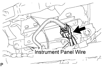
| 58. DISCONNECT INSTRUMENT PANEL WIRE ASSEMBLY |
Disconnect the connector (yellow colored one).
 |
| 59. REMOVE INSTRUMENT PANEL SAFETY PAD ASSEMBLY |
Disengage each clamp.
Disconnect each connector.
Remove the bolt <J>.
Remove the 2 passenger airbag bolts <K>.
with Plasmacluster:
Disconnect the connector.

Remove the 2 bolts <H> or <O>.
Remove the 2 nuts <C> or <I>.
Disengage the 5 claws and remove the instrument panel safety pad assembly.

| 60. REMOVE NO. 1 CONSOLE BOX DUCT (w/ Rear Register Duct) |
Remove the clip and No. 1 console box duct.
 |
| 61. REMOVE FLOOR CARPET BRACKET LH |
Release the clamp.
 |
Turn back the floor carpet.
Remove the 3 clips.
 |
Remove the floor carpet bracket LH.
| 62. REMOVE FLOOR CARPET BRACKET RH |
Release the clamp.
 |
Turn back the floor carpet.
Remove the 3 clips.
 |
Remove the floor carpet bracket RH.
| 63. REMOVE REAR NO. 2 AIR DUCT |
Release the 2 claws and remove the rear No. 2 air duct.
 |
| 64. REMOVE REAR NO. 1 AIR DUCT |
Release the 2 claws and remove the rear No. 1 air duct.
 |
| 65. REMOVE NO. 1 AIR DUCT |
Disengage the 2 claws and remove the No. 1 air duct.
 |
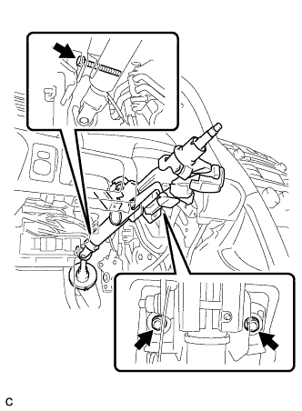
| 66. REMOVE STEERING COLUMN ASSEMBLY |
Remove the clamp from the steering column hole shield.
 |
Remove the bolt and slide the steering intermediate shaft assembly.
- NOTICE:
- Do not separate the steering intermediate shaft assembly from the power steering link assembly.
 |
Put matchmarks on the steering intermediate shaft assembly and the power steering link assembly.
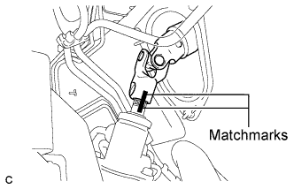 |
Separate the steering intermediate shaft assembly from the power steering link assembly.
Disconnect the connectors and wire harness clamps from the steering column assembly.
Remove the bolt, 2 nuts, and the steering column assembly.
 |
| 67. REMOVE AIR CONDITIONING AMPLIFIER ASSEMBLY |
Disconnect the 2 connectors.
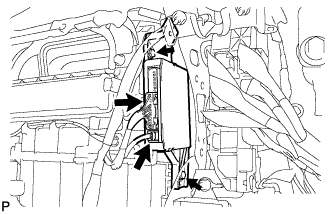 |
Remove the 2 bolts and air conditioning amplifier assembly.
| 68. REMOVE INSTRUMENT PANEL REINFORCEMENT ASSEMBLY |
Remove the 28 clamps, disconnect the 11 connectors, and then disconnect the wire harness.
Remove the 6 nuts, 7 bolts, and junction block.
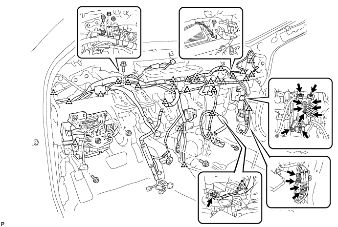
Remove the 2 caps and 2 bolts from the engine compartment side.
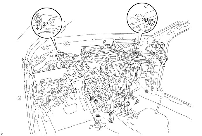
Remove the 2 bolts and nut.
Using a "TORX" socket wrench (T40), remove the 5 "TORX" bolts.
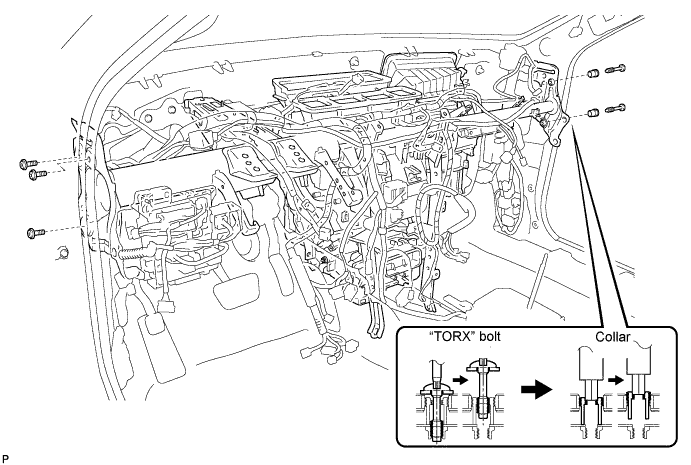
- HINT:
- The "TORX" bolts on the passenger side can be removed with the collars for adjustment.
Using a hexagon wrench 12 mm, remove the 2 collars and instrument panel reinforcement assembly with the air conditioner unit assembly.
Remove the 3 bolts, 2 screws, and instrument panel reinforcement assembly.
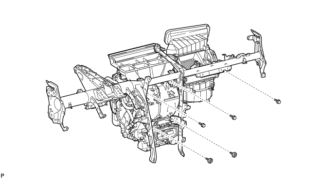
| 69. REMOVE BLOWER ASSEMBLY |
Disconnect the connector.
 |
Remove the 2 screws and blower assembly.