Air Conditioning System Steering Pad Switch Circuit
DESCRIPTION
WIRING DIAGRAM
INSPECTION PROCEDURE
INSPECT A/C CONTROL ASSEMBLY
INSPECT STEERING PAD SWITCH ASSEMBLY
INSPECT SPIRAL CABLE SUB-ASSEMBLY
CHECK HARNESS AND CONNECTOR (A/C CONTROL ASSEMBLY - SPIRAL CABLE SUB-ASSEMBLY)
AIR CONDITIONING SYSTEM - Steering Pad Switch Circuit |
DESCRIPTION
AUTO, OFF, TEMP UP (+), and TEMP DOWN (-) switches are located on the steering pad switch. The resistance of the steering pad switch changes in accordance with switch operation. The A/C control assembly (heater control base sub-assembly) outputs voltage to the steering pad switch and reads voltage changes due to the resistance changes that result from switch operation.- HINT:
- If there is an open in the circuit, the A/C system cannot be operated by the steering pad switch assembly.
- If there is a short in the circuit, the resulting condition is the same as if the switch were continuously depressed. Therefore, the A/C control assembly (heater control base sub-assembly) cannot be operated by the steering pad switch assembly, and the A/C control assembly (heater control base sub-assembly) will not be able to function correctly.
WIRING DIAGRAM
INSPECTION PROCEDURE
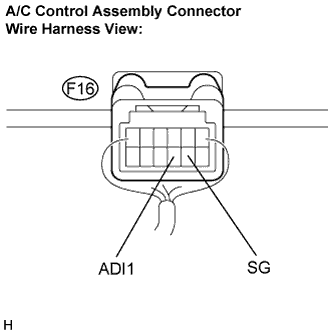
| 1.INSPECT A/C CONTROL ASSEMBLY |
Remove the A/C control assembly (heater control base sub-assembly) with the connectors still connected.
Measure the resistance according to the value(s) in the table below.
- Standard resistance:
Tester Connection (Symbols)
| Condition
| Specified Condition
|
F16-9 (ADI1) - F16-8 (SG)
| AUTO switch: ON
| Below 2.5 Ω
|
F16-9 (ADI1) - F16-8 (SG)
| OFF switch: ON
| Approx. 329 Ω
|
F16-9 (ADI1) - F16-8 (SG)
| TEMP+ switch: ON
| Approx. 1,000 Ω
|
F16-9 (ADI1) - F16-8 (SG)
| TEMP- switch: ON
| Approx. 3,110 Ω
|
| OK |
|
|
|
| PROCEED TO NEXT CIRCUIT INSPECTION SHOWN IN PROBLEM SYMPTOMS TABLE |
|
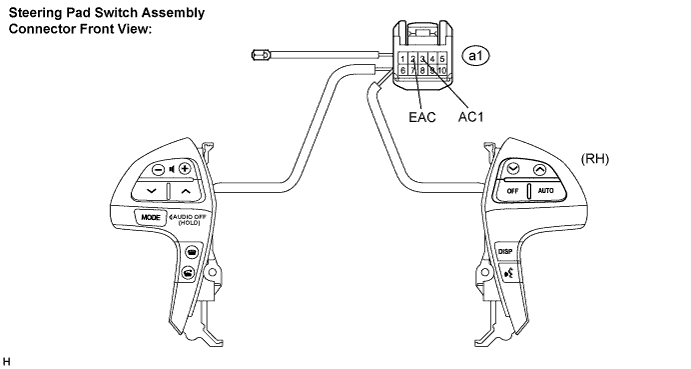
| 2.INSPECT STEERING PAD SWITCH ASSEMBLY |
Remove the steering pad switch assembly.
Disconnect the connector from the steering pad switch assembly.
Measure the resistance according to the value(s) in the table below.
- Standard resistance:
Tester Connection (Symbols)
| Condition
| Specified Condition
|
a1-3 (AC1) - a1-2 (EAC)
| AUTO switch: ON
| Below 2.5 Ω
|
a1-3 (AC1) - a1-2 (EAC)
| OFF switch: ON
| Approx. 329 Ω
|
a1-3 (AC1) - a1-2 (EAC)
| TEMP+ switch: ON
| Approx. 1,000 Ω
|
a1-3 (AC1) - a1-2 (EAC)
| TEMP- switch: ON
| Approx. 3,110 Ω
|
| | REPLACE STEERING PAD SWITCH ASSEMBLY |
|
|
| 3.INSPECT SPIRAL CABLE SUB-ASSEMBLY |
Disconnect the connector from the spiral cable sub-assembly.
Measure the resistance according to the value(s) in the table below.
- Standard resistance:
Tester Connection (Symbols)
| Condition
| Specified Condition
|
E18-10 (AC1) - a1-3 (AC1)
| Center
| Below 1 Ω
|
2.5 rotations to the left
|
2.5 rotations to the right
|
E18-9 (EAC) - a1-2 (EAC)
| Center
| Below 1 Ω
|
2.5 rotations to the left
|
2.5 rotations to the right
|
- HINT:
- The spiral cable makes a maximum of approximately 5 rotations.
| | REPLACE SPIRAL CABLE SUB-ASSEMBLY |
|
|
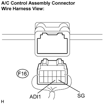
| 4.CHECK HARNESS AND CONNECTOR (A/C CONTROL ASSEMBLY - SPIRAL CABLE SUB-ASSEMBLY) |
Disconnect the connector from the A/C control assembly (heater control base sub-assembly).
Disconnect the connector from the spiral cable sub-assembly.
Measure the resistance according to the value(s) in the table below.
- Standard resistance:
Tester Connection
| Condition
| Specified Condition
|
F16-9 (ADI1) - E18-10 (AC1)
| Always
| Below 1 Ω
|
F16-8 (SG) - E18-9 (EAC)
| Always
| Below 1 Ω
|
F16-9 (ADI1) - E18-10 (AC1)
| Always
| 10 kΩ or higher
|
F16-8 (SG) - E18-9 (EAC)
| Always
| 10 kΩ or higher
|
| | REPAIR OR REPLACE HARNESS OR CONNECTOR |
|
|
| OK |
|
|
|
| REPLACE HEATER CONTROL BASE SUB-ASSEMBLY |
|