Heater & Air Conditioning System. Camry. Acv40 Gsv40
Air Conditioning. Camry. Acv40 Gsv40
Air Conditioning System -- Terminals Of Ecu |
| A/C AMPLIFIER |
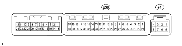
- HINT:
- Check from the rear of the connector while it is connected to the A/C amplifier.
| Terminal No. (Symbols) | Wiring Color | Terminal Description | Condition | Specified Condition |
| E38-1 (IG+) - E38-14 (GND) | V - W-B | Power source (IG) | Ignition switch: ON | 10 to 14 V |
| E38-1 (IG+) - E38-14 (GND) | V - W-B | Power source (IG) | Ignition switch: LOCK | Below 1 V |
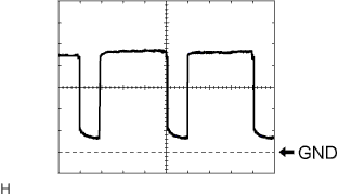
| E38-2 (SOL+) - E38-14 (GND) | W - W-B | A/C compressor operation signal | Engine is running A/C switch: ON Blower switch: LO | Pulse generation (See waveform 1) |
| E38-5 (TAM) - E38-14 (GND) | P - W-B | A/C ambient temperature sensor signal | Ignition switch: ON at 25°C (77°F) | 1.35 to 1.75 V |
| E38-5 (TAM) - E38-14 (GND) | P - W-B | A/C ambient temperature sensor signal | Ignition switch: ON at 40°C (104°F) | 0.9 to 1.2 V |
| E38-8 (LOCK)*1 - E38-14 (GND) | G - W-B | A/C compressor lock sensor signal | Engine is running Blower switch: LO A/C switch: ON | Pulse generation (See waveform 2) |
| E38-9 (PRE) - E38-13 (SG-2) | V - L | A/C pressure sensor signal | Start engine, Operate A/C system, Refrigerant pressure: Abnormal pressure (more than 3,140 kPa (32.0 kgf/cm2, 455 psi)) | 4.74 V or higher |
| E38-9 (PRE) - E38-13 (SG-2) | V - L | A/C pressure sensor signal | Start engine, Operate A/C system, Refrigerant pressure: Abnormal pressure (less than 196 kPa (2.0 kgf/cm2, 28 psi)) | Below 0.76 V |
| E38-9 (PRE) - E38-13 (SG-2) | V - L | A/C pressure sensor signal | Start engine, Operate A/C system, Refrigerant pressure: Abnormal pressure (more than 3,140 kPa (32.0 kgf/cm2, 455 psi) and less than 196 kPa (2.0 kgf/cm2, 28 psi)) | 0.76 to 4.74 V |
| E38-10 (S5-3) - E38-13 (SG-2) | BR - L | Power supply for A/C pressure sensor | Ignition switch: ON A/C switch: ON | 4.5 to 5.5 V |
| E38-10 (S5-3) - E38-13 (SG-2) | BR - L | Power supply for A/C pressure sensor | Ignition switch: ON A/C switch: OFF | Below 1 V |
| E38-11 (CANH) - E38-12 (CANL) | B - W | CAN communication system | CAN communication circuit | Pulse generation |
| E38-13 (SG-2) - Body ground | L - Body ground | Ground for A/C pressure sensor, A/C ambient temperature sensor, A/C lock sensor | Always | Below 1 V |
| E38-14 (GND) - Body ground | W-B - Body ground | Ground for main power supply | Always | Below 1 V |
| E38-20 (MGC)*1 - E38-14 (GND) | LG - W-B | A/C compressor magnetic clutch operation signal | Ignition switch: ON Blower switch: LO A/C switch: OFF | 10 to 14 V |
| E38-20 (MGC)*1 - E38-14 (GND) | LG - W-B | A/C compressor magnetic clutch operation signal | Ignition switch: ON Blower switch: LO A/C switch: ON | Below 1 V |
| E38-21 (B) - E38-14 (GND) | GR - W-B | Power source (Back-up) | Always | 10 to 14 V |
| E38-23 (BLW) - E38-14 (GND) | R - W-B | Blower motor speed control signal | Ignition switch: ON Blower switch: ON | Pulse generation (See waveform 3) |
| E38-29 (TR) - E38-34 (SG-1) | P - LG | A/C room temperature sensor signal | Ignition switch: ON Cabin temperature at 25°C (77°F) | 1.8 to 2.2 V |
| E38-29 (TR) - E38-34 (SG-1) | P - LG | A/C room temperature sensor signal | Ignition switch: ON Cabin temperature at 40°C (104°F) | 1.2 to 1.6 V |
| E38-32 (TSP) - E38-14 (GND) | Y - W-B | A/C solar sensor signal (for Front passenger side) | Ignition switch: ON Solar sensor is subjected to electric light. | 0.8 to 4.3 V |
| E38-32 (TSP) - E38-14 (GND) | Y - W-B | A/C solar sensor signal (for Front passenger side) | Ignition switch: ON Solar sensor is covered with a cloth. | Below 0.8 V |
| E38-33 (TSD) - E38-14 (GND) | O - W-B | A/C solar sensor signal (for Driver side) | Ignition switch: ON Solar sensor is subjected to electric light. | 0.8 to 4.3 V |
| E38-33 (TSD) - E38-14 (GND) | O - W-B | A/C solar sensor signal (for Driver side) | Ignition switch: ON Solar sensor is covered with a cloth. | Below 0.8 V |
| E38-34 (SG-1) - Body ground | LG - Body ground | Ground for A/C room temperature sensor | Always | Below 1 V |
| E38-37 (LIN1) - E38-14 (GND) | GR - W-B | LIN communication signal | Ignition switch: ON | Pulse generation |
| E38-38 (RDFG) - E38-14 (GND) | G - W-B | DEF relay signal | Ignition switch: ON REAR DEF switch: ON | Below 1 V |
| E38-38 (RDFG) - E38-14 (GND) | G - W-B | DEF relay signal | Ignition switch: ON REAR DEF switch: OFF | 10 to 14 V |
| E38-39 (PCD1) - E38-14 (GND) | R - W-B | PlasmaclusterTM operation signal (CLEAN mode) | Ignition switch: ON Blower switch: OFF (plasmaclusterTM not operating) | 10 to 14 V |
| E38-39 (PCD1) - E38-14 (GND) | R - W-B | PlasmaclusterTM operation signal (CLEAN mode) | Ignition switch: ON Blower switch: ON (plasmaclusterTM operating) | Below 1 V |
| E38-40 (PCD2) - E38-14 (GND) | B - W-B | PlasmaclusterTM operation signal (ION mode) | Ignition switch: ON Blower switch: OFF (plasmaclusterTM not operating) | 10 to 14 V |
| E38-40 (PCD2) - E38-14 (GND) | B - W-B | PlasmaclusterTM operation signal (ION mode) | Ignition switch: ON Blower switch: ON (plasmaclusterTM operating) | Below 1 V |
| e1-2 (BUS G) - Body ground | - | Ground for BUS IC | Always | Below 1 V |
| e1-3 (BUS) - e1-2 (BUS G) | - | BUS IC control signal | Ignition switch: LOCK → ON | Pulse generation |
| e1-4 (B BUS) - e1-2 (BUS G) | - | Power supply for BUS IC | Ignition switch: LOCK | Below 1 V |
| e1-4 (B BUS) - e1-2 (BUS G) | - | Power supply for BUS IC | Ignition switch: ON | 10 to 14 V |
| e1-5 (SGA) - Body ground | - | Ground for evaporator temperature sensor | Always | Below 1 V |
| e1-6 (TEA) - e1-5 (SGA) | - | A/C evaporator temperature sensor signal | Ignition switch: ON Evaporator temperature at 0°C (32°F) | 1.7 to 2.1 V |
| e1-6 (TEA) - e1-5 (SGA) | - | A/C evaporator temperature sensor signal | Ignition switch: ON Evaporator temperature at 15°C (59°F) | 0.9 to 1.3 V |
Waveform 1:
Item Contents Terminal No. (Symbols) E38-2 (SOL+) - E38-14 (GND) Tool Setting 5 V/DIV., 500 μs/DIV. Vehicle Condition Engine is running
A/C switch: ONWaveform 2:
Item Contents Terminal No. (Symbols) E38-8 (LOCK) - E38-14 (GND) Tool Setting 200 mV/DIV., 10 ms./DIV. Vehicle Condition Engine is running
Blower switch: LO
A/C switch: ONWaveform 3:
Item Contents Terminal No. (Symbols) E38-23 (BLW) - E38-14 (GND) Tool Setting 1 V/DIV., 500 μs/DIV. Vehicle Condition Ignition switch: ON
Blower switch: ON
 |
 |
 |
| A/C CONTROL ASSEMBLY (HEATER CONTROL BASE SUB-ASSEMBLY) |

- HINT:
- Check from the rear of the connector while it is connected to the A/C control assembly (heater control base sub-assembly).
| Terminal No. (Symbols) | Wiring Color | Terminal Description | Condition | Specified Condition |
| F16-3 (GND) - Body ground | W-B - Body ground | Ground for A/C control assembly (heater control base sub-assembly) | Always | Below 1 V |
| F16-4 (TX+) - F16-3 (GND) | L - W-B | LIN communication circuit | Ignition switch: ON | Pulse generation |
| F16-5 (IG+) - F16-3 (GND) | V - W-B | Power source (IG) | Ignition switch: LOCK | Below 1 V |
| F16-5 (IG+) - F16-3 (GND) | V - W-B | Power source (IG) | Ignition switch: ON | 10 to 14 V |