Skid Control Sensor Installation
Brake. Camry. Acv40 Gsv40
INSTALL SKID CONTROL SENSOR
INSTALL REAR AXLE HUB AND BEARING ASSEMBLY WITH SKID CONTROL SENSOR
INSPECT REAR AXLE HUB BEARING LOOSENESS
INSPECT REAR AXLE HUB RUNOUT
INSTALL REAR DISC
INSTALL REAR DISC BRAKE CALIPER ASSEMBLY
CONNECT SKID CONTROL SENSOR WIRE
INSTALL REAR WHEEL
INSPECT AND ADJUST REAR WHEEL ALIGNMENT
CHECK SPEED SENSOR SIGNAL
Skid Control Sensor -- Installation |
| 1. INSTALL SKID CONTROL SENSOR |
Clean the contact surface between the rear axle hub and bearing assembly and a new skid control sensor.
- NOTICE:
- Prevent foreign matter from attaching to the skid control sensor rotor.
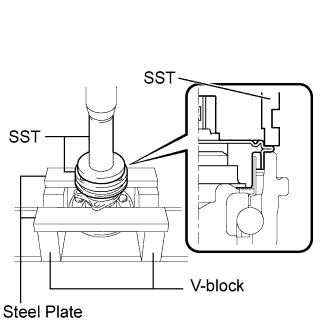
Place the skid control sensor on the rear axle hub and bearing assembly so that the connector is positioned as shown in the illustration.
Using SST, a press, 2 V-blocks, and 2 steel plates, install the skid control sensor to the rear axle hub and bearing assembly.
- SST
- 09309-36010
09213-58013
- NOTICE:
- Keep the skid control sensor away from magnets.
- Do not use a hammer on the skid control sensor.
- Check that there is no foreign matter such as iron chips on the detecting portion of the skid control sensor.
- Slowly press the skid control sensor straight.
| 2. INSTALL REAR AXLE HUB AND BEARING ASSEMBLY WITH SKID CONTROL SENSOR |
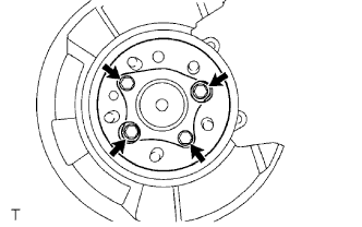
Install the hub and bearing assembly with the 4 bolts.
- Torque:
- 80 N*m{816 kgf*cm, 59 ft.*lbf}
Connect the skid control sensor connector.
- NOTICE:
- Do not twist the sensor wire when connecting it.
| 3. INSPECT REAR AXLE HUB BEARING LOOSENESS |
Using a dial indicator, check for looseness near the center of the axle hub.
- Maximum:
- 0.05 mm (0.0020 in.)
- NOTICE:
- Ensure that the dial indicator is set perpendicular to the measurement surface.
If looseness exceeds the maximum, replace the axle hub assembly.
| 4. INSPECT REAR AXLE HUB RUNOUT |
Using a dial indicator, check for runout on the surface of the axle hub outside the hub bolt.
- Maximum:
- 0.07 mm (0.0027 in.)
- NOTICE:
- Ensure that the dial indicator is set perpendicular to the measurement surface.
If runout exceeds the maximum, replace the axle hub assembly.
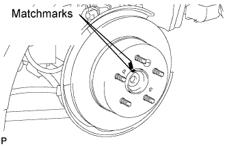
Aligning the matchmarks, install the rear disc.
- HINT:
- When replacing the rear disc with a new one, select the installation position where the rear disc has the minimum runout.
| 6. INSTALL REAR DISC BRAKE CALIPER ASSEMBLY |
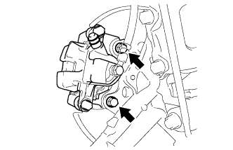
Install the rear disc brake caliper with the 2 bolts.
- Torque:
- 62 N*m{630 kgf*cm, 46 ft.*lbf}
- NOTICE:
- Do not twist the brake hose when installing the rear disc brake caliper assembly LH.
Install the rear flexible hose with the bolt.
- Torque:
- 19 N*m{192 kgf*cm, 14 ft.*lbf}
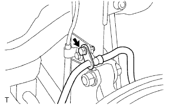
| 7. CONNECT SKID CONTROL SENSOR WIRE |
Connect the connector to the skid control sensor.
- Torque:
- 103 N*m{1,050 kgf*cm, 76 ft.*lbf}
| 9. INSPECT AND ADJUST REAR WHEEL ALIGNMENT |
- HINT:
- (CAMRY_ACV40 RM0000011DQ006X.html)
| 10. CHECK SPEED SENSOR SIGNAL |
- HINT:
- without VSC (CAMRY_ACV40 RM000001JBD003X.html)
- with VSC (CAMRY_ACV40 RM000000XHT00FX.html)