Dtc C0278/11 Open Or Short Circuit In Abs Solenoid Relay Circuit
Brake. Camry. Acv40 Gsv40
DESCRIPTION
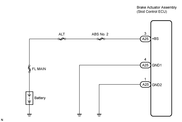
WIRING DIAGRAM
INSPECTION PROCEDURE
INSPECT FUSIBLE LINK (ABS NO. 2 FUSE)
INSPECT SKID CONTROL ECU CONNECTOR (+BS CIRCUIT)
INSPECT SKID CONTROL ECU CONNECTOR (GND TERMINAL CONTINUITY)
RECONFIRM DTC
DTC C0278/11 Open or Short Circuit in ABS Solenoid Relay Circuit |
DESCRIPTION
This relay supplies power to each ABS solenoid. If the ABS initial check is OK after the ignition switch is turned to the ON position, the skid control ECU will turn the ABS solenoid relay on.DTC No.
| DTC Detecting Condition
| Trouble Area
|
C0278/11
| When any of the following is detected:
- 3 or more solenoid valves are found faulty and simultaneously valve supply voltage is detected to be abnormal.
- Solenoid valve relay is not switched off.
- Valve relay is stuck open even through the valve relay supply voltage is high.
| - Wire harness (+BS circuit)
- ABS No. 2 fuse (Fusible link)
- Brake actuator assembly (Solenoid relay)
|
WIRING DIAGRAM
INSPECTION PROCEDURE
- HINT:
- When C1241/41 is output together with C0278/11, inspect and repair the trouble areas indicated by C1241/41 (CAMRY_ACV40 RM000001JD200KX.html).
- Check the condition of each related circuit before troubleshooting (CAMRY_ACV40 RM000000UZ301ZX.html).
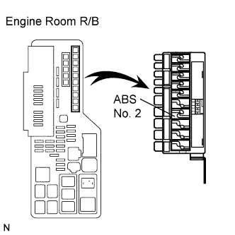
| 1.INSPECT FUSIBLE LINK (ABS NO. 2 FUSE) |
Remove the fusible link from the engine room R/B.
Check if the fusible link is melted.
- OK:
- The fusible link is not melted.
Install the fusible link to the engine room R/B with the nut.
- Torque:
- 5.4 N*m{55 kgf*cm, 48 in.*lbf}
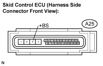
| 2.INSPECT SKID CONTROL ECU CONNECTOR (+BS CIRCUIT) |
Disconnect the skid control ECU connector.
Measure the voltage according to the value(s) in the table below.
- Standard voltage:
Tester Connection
| Condition
| Specified Condition
|
A25-3 (+BS) -
Body ground
| Always
| 10 to 14 V
|
| | REPAIR OR REPLACE HARNESS OR CONNECTOR (+BS CIRCUIT) |
|
|
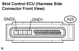
| 3.INSPECT SKID CONTROL ECU CONNECTOR (GND TERMINAL CONTINUITY) |
Measure the resistance according to the value(s) in the table below.
- Standard resistance:
Tester Connection
| Specified Condition
|
A25-4 (GND1) - Body ground
| Below 1 Ω
|
A25-1 (GND2) - Body ground
| Below 1 Ω
|
Connect the connector.
| | REPAIR OR REPLACE HARNESS OR CONNECTOR (GND CIRCUIT) |
|
|
- HINT:
- This code is detected when a problem is identified in the brake actuator assembly.
- The solenoid circuit is in the brake actuator assembly.
- Therefore, solenoid circuit inspection and solenoid unit inspection cannot be performed. Be sure to check if the DTC is output before replacing the brake actuator assembly.
Clear the DTC (CAMRY_ACV40 RM000001JB800LX.html).
Start the engine.
Drive the vehicle at a speed of 20 km/h (12 mph) or more for 30 seconds or more.
Check if the same DTC is recorded (CAMRY_ACV40 RM000001JB800LX.html).
- HINT:
- Reinstall the sensors, connectors, etc. and restore the vehicle to its prior condition before rechecking for DTCs.
- Result:
Condition
| Proceed to
|
DTC is not output
| A
|
DTC is output
| B
|
- HINT:
- If the normal system code is output (the trouble code is not output), slightly jiggle the connectors, wire harnesses, and fuses of the brake actuator assembly. Make sure that no DTCs are output.
- If any DTCs are output while jiggling a connector or wire harness of the brake actuator (skid control ECU), inspect and repair the connector or wire harness.
- It is suspected that the DTCs were output due to a bad connection of the connector terminal.