Front Stabilizer Bar Installation
INSTALL FRONT NO. 1 STABILIZER BAR BUSHING
INSTALL FRONT NO. 1 STABILIZER BRACKET LH
INSTALL FRONT NO. 1 STABILIZER BRACKET RH
INSTALL FRONT STABILIZER BAR
INSTALL ENGINE ASSEMBLY WITH TRANSAXLE
INSTALL FRONT STABILIZER LINK ASSEMBLY LH
INSTALL FRONT STABILIZER LINK ASSEMBLY RH
CONNECT TIE ROD END SUB-ASSEMBLY
CONNECT STEERING SLIDING YOKE
PLACE FRONT WHEELS FACING STRAIGHT
INSTALL FRONT WHEELS
CONNECT CABLE TO NEGATIVE BATTERY TERMINAL
INSPECT AND ADJUST FRONT WHEEL ALIGNMENT
Front Stabilizer Bar -- Installation |
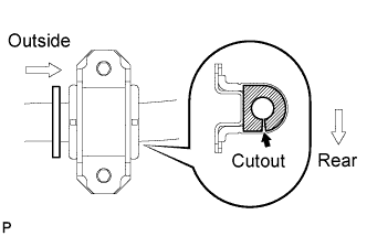
| 1. INSTALL FRONT NO. 1 STABILIZER BAR BUSHING |
Install the 2 front stabilizer bar bushings No. 1 to the outside of the bushing stopper on the front stabilizer bar.
- NOTICE:
- Make sure that the cutout of the front stabilizer bar bushing No. 1 faces the rear side as shown in the illustration.
| 2. INSTALL FRONT NO. 1 STABILIZER BRACKET LH |
Install the front No. 1 stabilizer bracket LH.
| 3. INSTALL FRONT NO. 1 STABILIZER BRACKET RH |
Install the front No. 1 stabilizer bracket RH.
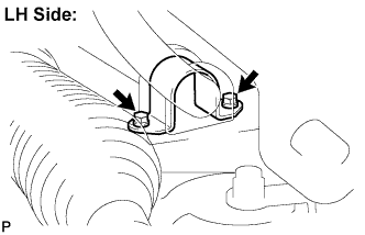
| 4. INSTALL FRONT STABILIZER BAR |
Install the front stabilizer bar with the 2 bolts. (LH Side)
- Torque:
- 16 N*m{163 kgf*cm, 12 ft.*lbf}
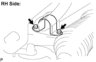
Install the front stabilizer bar with the 2 bolts. (RH Side)
- Torque:
- 16 N*m{163 kgf*cm, 12 ft.*lbf}
| 5. INSTALL ENGINE ASSEMBLY WITH TRANSAXLE |
- HINT:
- Refer to the instructions for installation of the engine assembly (CAMRY_ACV40 RM000000YIK010X_01_0026.html for 2GR-FE )
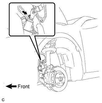
| 6. INSTALL FRONT STABILIZER LINK ASSEMBLY LH |
Install the front stabilizer link assembly LH with the 2 nuts.
- Torque:
- 74 N*m{755 kgf*cm, 55 ft.*lbf}
- HINT:
- If the ball joint turns together with the nut, use a hexagon (6 mm) wrench to hold the stud.
| 7. INSTALL FRONT STABILIZER LINK ASSEMBLY RH |
Install the front stabilizer link assembly RH with the 2 nuts.
- Torque:
- 74 N*m{755 kgf*cm, 55 ft.*lbf}
- HINT:
- If the ball joint turns together with the nut, use a hexagon (6 mm) wrench to hold the stud.
| 8. CONNECT TIE ROD END SUB-ASSEMBLY |
Install the tie rod end sub-assembly to the steering knuckle with the nut.
- Torque:
- 49 N*m{500 kgf*cm, 36 ft.*lbf}
Install a new cotter pin.
- NOTICE:
- If the holes for the cotter pin are not aligned, tighten the nut up to 60° further.
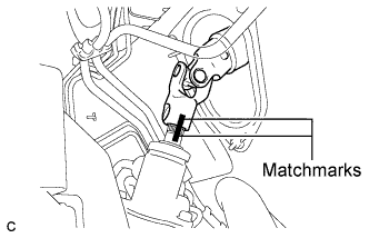
| 9. CONNECT STEERING SLIDING YOKE |
Align the matchmarks on the steering sliding yoke and the steering link assembly.
Install the bolt.
- Torque:
- 35 N*m{360 kgf*cm, 26 ft.*lbf}
| 10. PLACE FRONT WHEELS FACING STRAIGHT |
- Torque:
- 103 N*m{1,050 kgf*cm, 76 ft.*lbf}
| 12. CONNECT CABLE TO NEGATIVE BATTERY TERMINAL |
| 13. INSPECT AND ADJUST FRONT WHEEL ALIGNMENT |
(CAMRY_ACV40 RM0000011DA01NX.html)