INSTALL FRONT AXLE OUTBOARD JOINT BOOT CLAMP (except TMC Made 2AZ-FE)
INSTALL FRONT AXLE OUTBOARD JOINT BOOT CLAMP (for TMC Made 2AZ-FE)
INSTALL NO. 2 FRONT AXLE OUTBOARD JOINT BOOT CLAMP (except TMC Made 2AZ-FE)
INSTALL NO. 2 FRONT AXLE OUTBOARD JOINT BOOT CLAMP (for TMC Made 2AZ-FE)
INSTALL FRONT DRIVE SHAFT DAMPER LH (for TMC Made 2AZ-FE, Automatic Transaxle)
INSTALL FRONT DRIVE SHAFT DAMPER LH (for TMMR Made 2AZ-FE, Automatic Transaxle)
INSTALL NO. 2 FRONT AXLE INBOARD JOINT BOOT CLAMP (for 2GR-FE)
INSTALL FRONT AXLE INBOARD JOINT BOOT CLAMP (for TMC Made 2AZ-FE)
INSTALL NO. 2 FRONT AXLE INBOARD JOINT BOOT CLAMP (for TMC Made 2AZ-FE)
INSTALL FRONT AXLE INBOARD JOINT BOOT CLAMP (for TMMR Made 2AZ-FE)
INSTALL NO. 2 FRONT AXLE INBOARD JOINT BOOT CLAMP (for TMMR Made 2AZ-FE)
Front Drive Shaft -- Reassembly |
| 1. INSTALL FRONT DRIVE SHAFT BEARING |
Install a new bearing bracket hole snap ring to the front drive shaft assembly RH.
 |
Using SST and a steel plate, install a new front drive shaft bearing.
- SST
- 09527-30010
09527-10011
- NOTICE:
- Bearing should be completely installed.
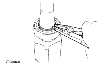
Using a snap ring expander, install a new drive shaft hole snap ring.
 |
| 2. INSTALL FRONT DRIVE SHAFT DUST COVER |
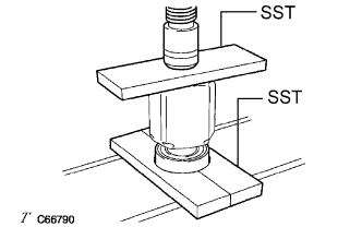
Using SST and a press, install a new drive shaft dust cover.
- SST
- 09726-40010
09527-10011
- NOTICE:
- The dust cover should be completely installed.
- Be careful not to damage the dust deflector.
 |
| 3. INSTALL FRONT DRIVE SHAFT DUST COVER RH |
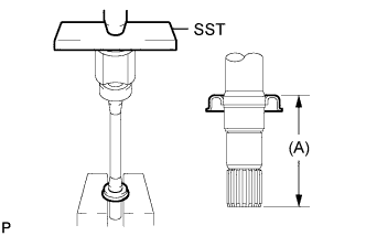
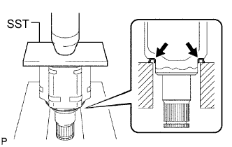
Using SST and a press, install a new drive shaft dust cover RH until distance (A) from the tip of the center drive shaft to the drive shaft dust cover RH meets the specification.
- SST
- 09527-10011
Engine type Distance (A) 2GR-FE 110.0 to 111.0 mm (4.3307 to 4.3701 in.) TMC Made 2AZ-FE 91.0 to 92.0 mm (3.5827 to 3.6220 in.) TMMR Made 2AZ-FE 91.4 to 91.6 mm (3.5984 to 3.6063 in.) - NOTICE:
- The dust cover should be completely installed.
- Be careful not to damage the dust deflector.
 |
| 4. INSTALL FRONT DRIVE SHAFT DUST COVER LH |
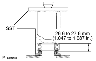
Using SST and a press, install a new drive shaft dust cover LH.
- SST
- 09527-10011
- NOTICE:
- The dust cover should be completely installed.
- Be careful not to damage the dust deflector.
 |
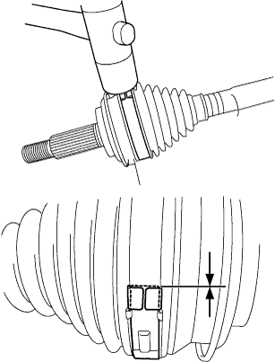
| 5. INSTALL FRONT AXLE OUTBOARD JOINT BOOT |
Hold the drive shaft lightly in a vise between aluminium plates.
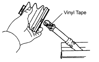
- HINT:
- Before installing the boots, wrap the spline of the drive shaft with vinyl tape to prevent the boots from being damaged.
 |
Temporarily install a new outboard joint boot to the drive shaft with the 2 clamps.
Pack the outboard joint shaft and boot with grease.
Engine type Grease capacity 2GR-FE 164 to 184 g (5.8 to 6.5 oz.) TMC Made 2AZ-FE 190 to 200 g (6.7 to 7.1 oz.) TMMR Made 2AZ-FE 105 to 125 g (3.7 to 4.4 oz.)
| 6. INSTALL FRONT AXLE OUTBOARD JOINT BOOT CLAMP (except TMC Made 2AZ-FE) |
Hold the drive shaft lightly in a vise between aluminum plates.
- NOTICE:
- Do not overtighten the vise.
 |
Install the 2 outboard joint boot clamps onto the boot.
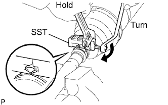
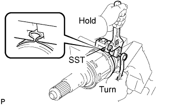
Place SST onto the outboard joint boot clamp.
- SST
- 09521-24010
Tighten SST so that the outboard joint boot clamp is pinched.
- NOTICE:
- Do not overtighten SST.
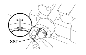
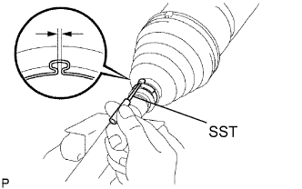
Using SST, measure the clearance of the outboard joint boot clamp.
- SST
- 09240-00020
- Clearance:
- 0.5 to 1.5 mm (0.0197 to 0.0591 in.)
- NOTICE:
- If the measured value is greater than the specified value, retighten the clamp.
 |
| 7. INSTALL FRONT AXLE OUTBOARD JOINT BOOT CLAMP (for TMC Made 2AZ-FE) |
Install the front axle outboard joint boot clamp onto the outboard joint boot and temporarily fold back the lever.
- CAUTION:
- Wear protective gloves. Sharp areas on the parts may injure your hands.
- NOTICE:
- Set the lever into the guide groove correctly.
- Check the band and the lever for any deformation before folding back the lever.
 |
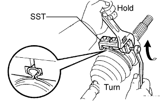
Using water pump pliers, pinch the boot clamp to temporarily secure it.
 |
Using a plastic hammer, tap the buckle to secure it while adjusting the clearance between the lever and the groove to make the clearance between the buckle edge and the lever end even.
- NOTICE:
- Do not damage the outboard joint boot.
 |
| 8. INSTALL NO. 2 FRONT AXLE OUTBOARD JOINT BOOT CLAMP (except TMC Made 2AZ-FE) |
Install the No. 2 outboard joint boot clamp onto the boot.
Place SST onto the No. 2 outboard joint boot clamp.
- SST
- 09521-24010
 |
Tighten SST so that the No. 2 outboard joint boot clamp is pinched.
- NOTICE:
- Do not overtighten SST.
Using SST, measure the clearance of the No. 2 outboard joint boot clamp.
- SST
- 09240-00020
- Clearance:
- 0.5 to 1.5 mm (0.0197 to 0.0591 in.)
- NOTICE:
- If the measured value is greater than the specified value, retighten the clamp.
 |
| 9. INSTALL NO. 2 FRONT AXLE OUTBOARD JOINT BOOT CLAMP (for TMC Made 2AZ-FE) |
Install the No. 2 front axle outboard joint boot clamp onto the outboard joint boot and temporarily fold back the lever.
- CAUTION:
- Wear protective gloves. Sharp areas on the parts may injure your hands.
- NOTICE:
- Set the lever into the guide groove correctly and install the clamp as far into the inside of the vehicle as possible.
- Check the band and the lever for any deformation before folding back the lever.
 |
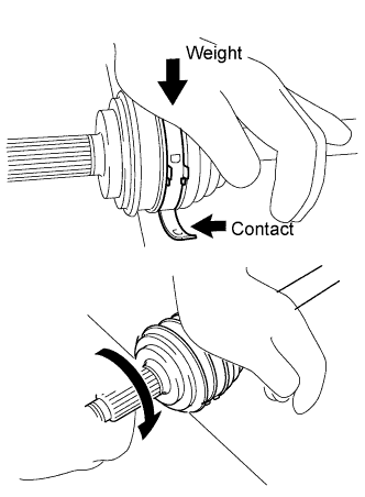
Lean your weight on your hand and roll the outboard joint forward while pressing the outboard joint against the work plane. Roll the outboard joint and fold the lever until a click sound can be heard.
- NOTICE:
- Do not damage the deflector.
- Make sure that the outboard joint is in direct contact with the work plane.
 |
Using a plastic hammer, tap the buckle to secure it while adjusting the clearance between the lever and the groove to make the clearance between the buckle edge and the lever end even.
- NOTICE:
- Do not damage the outboard joint boot.
 |
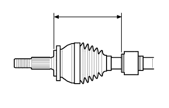
| 10. INSTALL FRONT DRIVE SHAFT DAMPER LH (for 2GR-FE) |
Install the drive shaft damper to the drive shaft.
 |
Make sure that the damper is on the shaft groove.
Set the distance as specified below.
- Distance:
- 228.0 to 232.0 mm (8.976 to 9.134 in.)
Install the drive shaft damper clamp onto the drive shaft damper.
- NOTICE:
- Be sure to install the clamp in the correct position.
Place SST onto the drive shaft damper clamp.
- SST
- 09521-24010
 |
Tighten SST so that the clamp is pinched.
- NOTICE:
- Do not overtighten SST.
Using SST, measure the clearance of the drive shaft damper clamp.
- SST
- 09240-00020
- Clearance:
- 0.5 to 1.5 mm (0.0197 to 0.0591 in.)
- NOTICE:
- If the measured value is greater than the specified value, retighten the clamp.
 |
| 11. INSTALL FRONT DRIVE SHAFT DAMPER RH (for 2GR-FE) |
Install the front drive shaft damper RH.
- HINT:
- Perform the same procedure as for the front drive shaft damper LH.
| 12. INSTALL FRONT DRIVE SHAFT DAMPER LH (for TMC Made 2AZ-FE, Automatic Transaxle) |
Install the drive shaft damper to the drive shaft.
|
Make sure that the damper is on the shaft groove.
Set the distance as specified below.
- Distance:
- 222.0 to 226.0 mm (8.740 to 8.898 in.)
Using a screwdriver, install a new drive shaft damper clamp as shown in the illustration.
 |
| 13. INSTALL FRONT DRIVE SHAFT DAMPER RH (for TMC Made 2AZ-FE) |
Install the drive shaft damper to the drive shaft.
|
Make sure that the damper is on the shaft groove.
Set the distance as specified below.
- Distance:
- 223.4 to 227.4 mm (8.795 to 8.953 in.)
Using a screwdriver, install a new drive shaft damper clamp as shown in the illustration.
|
| 14. INSTALL FRONT DRIVE SHAFT DAMPER LH (for TMMR Made 2AZ-FE, Automatic Transaxle) |
Install the drive shaft damper to the drive shaft.
 |
Make sure that the damper is on the shaft groove.
Set the distance as specified below.
- Distance:
- 228.0 to 232.0 mm (8.976 to 9.134 in.)
Install the drive shaft damper clamp onto the drive shaft damper.
- NOTICE:
- Be sure to install the clamp in the correct position.
Place SST onto the drive shaft damper clamp.
- SST
- 09521-24010
|
Tighten SST so that the clamp is pinched.
- NOTICE:
- Do not overtighten SST.
Using SST, measure the clearance of the drive shaft damper clamp.
- SST
- 09240-00020
- Clearance:
- 0.5 to 1.5 mm (0.0197 to 0.0591 in.)
- NOTICE:
- If the measured value is greater than the specified value, retighten the clamp.
 |
| 15. INSTALL FRONT DRIVE SHAFT DAMPER RH (for TMMR Made 2AZ-FE) |
Install the front drive shaft damper RH.
- HINT:
- Perform the same procedure as for the front drive shaft damper LH.
| 16. INSTALL FRONT DRIVE INBOARD JOINT ASSEMBLY |
Temporarily install a new inboard joint boot to the drive shaft with the 2 clamps.
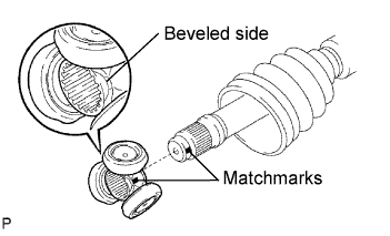 |
Place the beveled side of the tripod joint axial spline toward the outboard joint shaft.
Align the matchmarks.
Using a brass bar and hammer, tap in the tripod joint to the outboard joint shaft.
- NOTICE:
- Do not tap the roller.
- Be sure to install the tripod joint assembly in the correct direction.
Using a snap ring expander, install a new shaft snap ring.
 |
Coat the outboard joint shaft and boot with grease.
Engine type Grease capacity 2GR-FE 155 to 175 g (5.5 to 6.2 oz.) TMC Made 2AZ-FE 175 to 185 g (6.2 to 6.5 oz.) TMMR Made 2AZ-FE 170 to 190 g (6.0 to 6.7 oz.)
Align the matchmarks and install the inboard joint assembly to the outboard joint shaft assembly.
 |
| 17. INSTALL FRONT AXLE INBOARD JOINT BOOT |
Install the inboard joint boot to the inboard joint assembly.
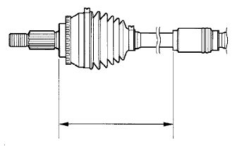
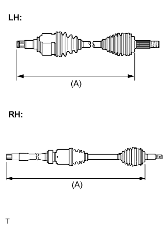
Check whether the drive shaft dimensions are within the following specifications.
- HINT:
- The following table shows dimension (A) of the drive shaft.
- Dimension (A):
Engine Type LH RH 2GR-FE 585.5 to 589.5 mm (23.05 to 23.21 in.) 904.4 to 908.4 mm (35.61 to 35.76 in.) TMC Made 2AZ-FE 592.2 to 602.2 mm (23.32 to 23.71 in.) 891.0 to 901.0 mm (35.08 to 35.47 in.) TMMR Made 2AZ-FE 598.0 to 602.0 mm (23.54 to 23.70 in.) 897.0 to 901.0 mm (35.31 to 35.47 in.)
 |
| 18. INSTALL FRONT AXLE INBOARD JOINT BOOT CLAMP (for 2GR-FE) |
Hold the drive shaft lightly in a vise between aluminum plates.
- NOTICE:
- Do not overtighten the vise.
 |
Install the 2 inboard joint boot clamps onto the boot.
Place SST onto the inboard joint boot clamp.
- SST
- 09521-24010
Tighten SST so that the inboard joint boot clamp is pinched.
- NOTICE:
- Do not overtighten SST.
Using SST, measure the clearance of the inboard joint boot clamp.
- SST
- 09240-00020
- Clearance:
- 0.5 to 1.5 mm (0.0197 to 0.0591 in.)
- NOTICE:
- If the measured value is greater than the specified value, retighten the clamp.
 |
| 19. INSTALL NO. 2 FRONT AXLE INBOARD JOINT BOOT CLAMP (for 2GR-FE) |
Hold the inboard joint shaft assembly in a vise between aluminium plates.
- NOTICE:
- Do not overtighten the vise.
Install the No. 2 front axle inboard joint boot clamp onto the boot.
Place SST onto the No. 2 front axle inboard joint boot clamp.
- SST
- 09521-24010
 |
Tighten SST so that the No. 2 front axle inboard joint boot clamp is pinched.
- NOTICE:
- Do not overtighten SST.
Using SST, measure the clearance of the No. 2 front axle inboard joint boot clamp.
- SST
- 09240-00020
- Clearance:
- 0.5 to 1.5 mm (0.0197 to 0.0591 in.)
- NOTICE:
- If the measured value is greater than the specified value, retighten the clamp.
 |
| 20. INSTALL FRONT AXLE INBOARD JOINT BOOT CLAMP (for TMC Made 2AZ-FE) |
For one touch type:
Using a screwdriver, install the inboard joint boot clamp as shown in the illustration.
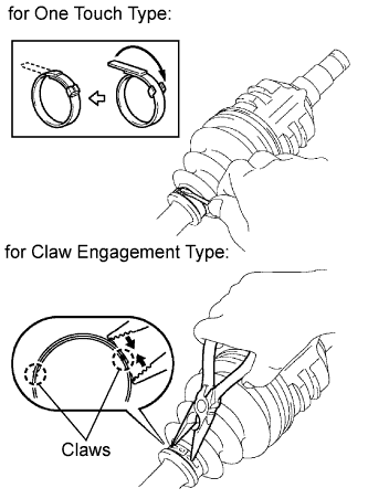 |
For claw engagement type:
Using needle-nose pliers, install the inboard joint boot clamp as shown in the illustration.
| 21. INSTALL NO. 2 FRONT AXLE INBOARD JOINT BOOT CLAMP (for TMC Made 2AZ-FE) |
For one touch type:
Using a screwdriver, install the No. 2 front axle inboard joint boot clamp as shown in the illustration.
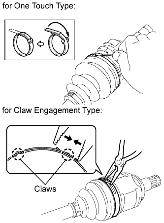 |
For claw engagement type:
Using needle-nose pliers, install the No. 2 front axle inboard joint boot clamp as shown in the illustration.
| 22. INSTALL FRONT AXLE INBOARD JOINT BOOT CLAMP (for TMMR Made 2AZ-FE) |
Hold the drive shaft lightly in a vise between aluminum plates.
- NOTICE:
- Do not overtighten the vise.
Install the 2 inboard joint boot clamps onto the boot.
Place SST onto the inboard joint boot clamp.
- SST
- 09521-24010
 |
Tighten SST so that the inboard joint boot clamp is pinched.
- NOTICE:
- Do not overtighten SST.
Using SST, measure the clearance of the inboard joint boot clamp.
- SST
- 09240-00020
- Clearance:
- 0.5 to 1.5 mm (0.0197 to 0.0591 in.)
- NOTICE:
- If the measured value is greater than the specified value, retighten the clamp.
 |
| 23. INSTALL NO. 2 FRONT AXLE INBOARD JOINT BOOT CLAMP (for TMMR Made 2AZ-FE) |
Using needle-nose pliers, install the new No. 2 front axle inboard joint boot clamp as shown in the illustration.
- NOTICE:
- Be careful not to damage the boot.
 |
| 24. INSTALL FRONT DRIVE SHAFT LH HOLE SNAP RING |
Install a new hole snap ring.
| 25. INSPECT FRONT DRIVE SHAFT ASSEMBLY |
Check that there is no excessive play in the outboard joint.
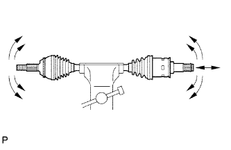 |
Check that the inboard joint slides smoothly in the thrust direction.
Check that there is no excessive play in the radial directions of the inboard joint.
Check the boots for damage.