Automatic Transaxle Unit Reassembly
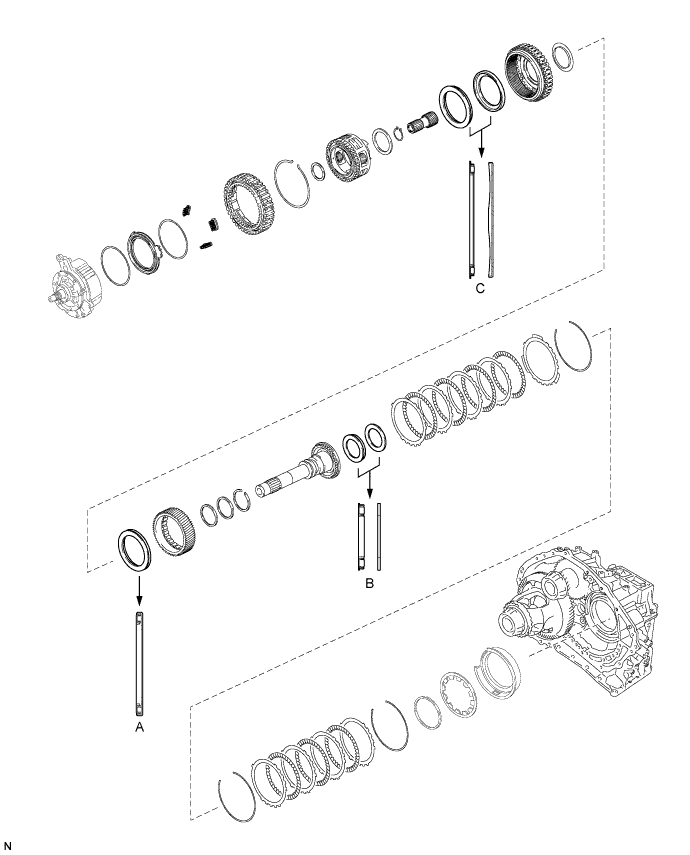
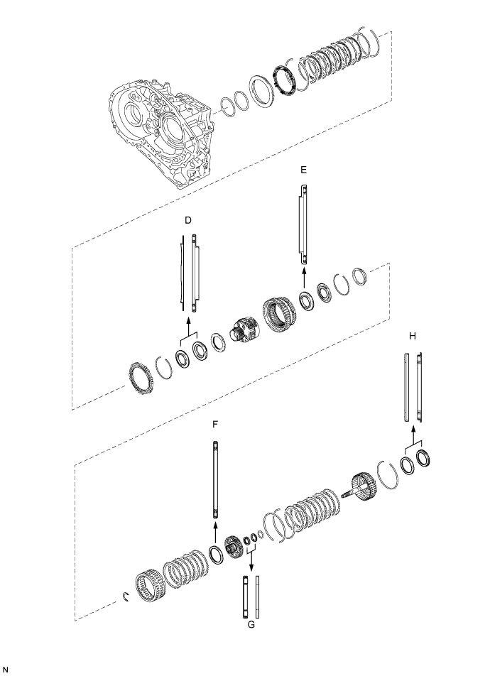
BEARING POSITION
INSTALL MANUAL VALVE LEVER SHAFT OIL SEAL
INSTALL MANUAL VALVE LEVER SHAFT
INSTALL PARKING LOCK ROD SUB-ASSEMBLY
INSTALL MANUAL DETENT SPRING SUB-ASSEMBLY
INSTALL COUNTER DRIVE GEAR BEARING
INSTALL NO. 3 BRAKE PISTON
INSTALL COUNTER DRIVE GEAR
INSTALL FRONT PLANETARY GEAR ASSEMBLY
INSTALL NO. 2 BRAKE PISTON
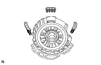
INSTALL 1ST AND REVERSE BRAKE RETURN SPRING SUB-ASSEMBLY
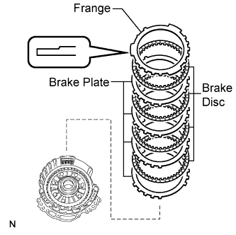
INSTALL NO. 2 BRAKE DISC
INSPECT CLEARANCE OF NO. 2 BRAKE
INSTALL PLANETARY RING GEAR FLANGE
INSTALL PLANETARY RING GEAR
INSTALL ONE-WAY CLUTCH ASSEMBLY
INSTALL COUNTER DRIVEN GEAR REAR TAPERED ROLLER BEARING OUTER RACE
INSTALL PARKING LOCK PAWL
INSTALL PARKING LOCK SLEEVE
INSTALL PAWL STOPPER PLATE
INSTALL PAWL SHAFT CLAMP
INSTALL COUNTER DRIVEN GEAR FRONT TAPERED ROLLER BEARING
INSTALL COUNTER DRIVEN GEAR REAR TAPERED ROLLER BEARING
INSTALL COUNTER DRIVEN GEAR
INSTALL COUNTER DRIVE GEAR NUT
INSTALL FRONT DIFFERENTIAL CASE
INSPECT DIFFERENTIAL SIDE GEAR
INSTALL NO. 1 BRAKE PISTON
INSTALL 2ND BRAKE PISTON RETURN SPRING SUB-ASSEMBLY
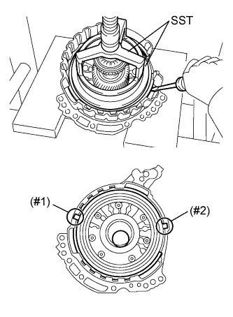
INSTALL NO. 1 BRAKE DISC
INSPECT CLEARANCE OF NO. 1 BRAKE
INSTALL UNDERDRIVE PLANETARY SUN GEAR
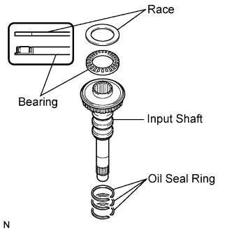
INSTALL INPUT SHAFT SUB-ASSEMBLY
INSTALL PLANETARY SUN GEAR SUB-ASSEMBLY
INSTALL UNDERDRIVE PLANETARY RING GEAR
INSTALL NO. 3 BRAKE HUB
INSTALL UNDERDRIVE PLANETARY GEAR ASSEMBLY
INSTALL NO. 3 BRAKE DISC
INSPECT CLEARANCE OF NO. 3 BRAKE
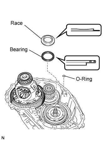
INSTALL FRONT OIL PUMP AND GEAR BODY SUB-ASSEMBLY
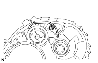
INSTALL DIFFERENTIAL GEAR LUBE APPLY TUBE
INSTALL COUNTER DRIVEN GEAR FRONT TAPERED ROLLER BEARING OUTER RACE
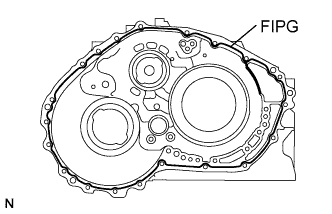
INSTALL TRANSAXLE HOUSING
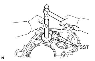
ADJUST COUNTER DRIVEN GEAR PRELOAD
INSTALL NO. 1 CLUTCH DISC
INSPECT CLEARANCE OF NO. 1 CLUTCH DISC
INSTALL REAR PLANETARY SUN GEAR ASSEMBLY
INSTALL NO. 2 CLUTCH DISC
INSTALL DIRECT MULTIPLE DISC CLUTCH SNAP RING
INSPECT CLEARANCE OF NO. 2 CLUTCH DISC
INSTALL REAR MULTIPLE DISC CLUTCH ASSEMBLY
INSTALL TRANSAXLE REAR COVER SUB-ASSEMBLY
INSPECT INPUT SHAFT END PLAY
INSTALL TRANSAXLE CASE GASKET
INSTALL TRANSMISSION VALVE BODY ASSEMBLY
INSTALL VALVE BODY OIL STRAINER ASSEMBLY
INSTALL AUTOMATIC TRANSAXLE OIL PAN SUB-ASSEMBLY
INSTALL NO. 1 TRANSAXLE CASE PLUG
INSTALL OIL COOLER TUBE UNION (OUTLET OIL COOLER UNION)
INSTALL OIL COOLER TUBE UNION (INLET OIL COOLER UNION)
INSTALL PARK/NEUTRAL POSITION SWITCH ASSEMBLY
INSTALL BREATHER PLUG HOSE
Automatic Transaxle Unit -- Reassembly |
Mark
| Front Race Diameter
Inside / Outside mm (in.)
| Thrust Bearing Diameter
Inside / Outside mm (in.)
| Rear Race Diameter
Inside / Outside mm (in.)
|
A
| -
| 57.7 (2.271) / 75.2 (2.961)
| -
|
B
| -
| 29.1 (1.146) / 48.6 (1.913)
| 30.7 (1.209) / 48.3 (1.902)
|
C
| 65.9 (2.594) / 80.3 (3.161)
| 62.6 (2.465) / 82.4 (3.244)
| -
|
D
| 59.4 (2.339) / 77 (3.032)
| 53.1 (2.091) / 79 (3.110)
| -
|
E
| -
| 56.1 (2.209) / 80.9 (3.185)
| -
|
F
| -
| 61.2 (2.409) / 79 (3.110)
| -
|
G
| -
| 28 (1.102) / 47.1 (1.854)
| 26.1 (1.028) / 44 (1.732)
|
H
| 52.2 (2.055) / 70.4 (2.772)
| 48.9 (1.925) / 72.0 (2.835)
| -
|
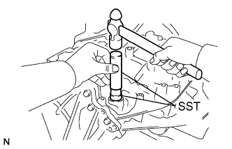
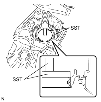
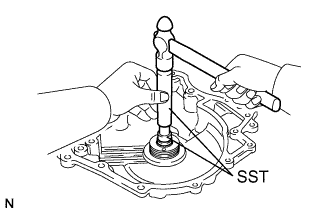
| 2. INSTALL MANUAL VALVE LEVER SHAFT OIL SEAL |
Coat the lip of a new manual valve lever shaft oil seal with MP grease.
Using SST and a hammer, install the manual valve lever shaft oil seal to the transaxle case.
- SST
- 09950-60010(09951-00230)
09950-70010(09951-07100)
- Oil seal installation depth:
- -0.5 to 0.5 mm (-0.0197 to 0.0197 in.)
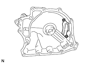
| 3. INSTALL MANUAL VALVE LEVER SHAFT |
Install a new spacer to the parking lock lever sub-assembly.
Install the parking lock lever sub-assembly to the manual valve lever shaft.
Install a new spacer to the manual valve lever sub-assembly.
Install the manual valve lever sub-assembly to the manual valve lever shaft.
Install the manual valve lever shaft to the transaxle case.
- NOTICE:
- Do not damage the manual valve lever shaft oil seal while installing the manual valve lever shaft to the transaxle case.
Using a pin punch (3 mm) and hammer, install a new slotted spring pin to the parking lock lever sub-assembly.
Turn the spacer and the lever shaft to align the smaller hole of the spacer with the staking position mark on the lever shaft.
Using a pin punch, stake the spacer through the small hole.
Check that the spacer does not turn.
Using a pin punch (3 mm) and hammer, install a new slotted spring pin to the manual valve lever sub-assembly.
Turn the spacer and the lever shaft to align the smaller hole of the spacer with the staking position mark on the lever shaft.
Using a pin punch, stake the spacer through the small hole.
Check that the spacer does not turn.
Using needle-nose pliers, install the manual valve shaft retainer spring to the transaxle case.
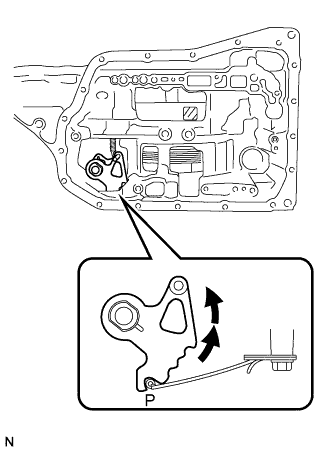
| 4. INSTALL PARKING LOCK ROD SUB-ASSEMBLY |
Align the dial with the notches on the parking lock lever sub-assembly and install the parking lock rod sub-assembly.
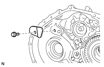
| 5. INSTALL MANUAL DETENT SPRING SUB-ASSEMBLY |
Install the manual detent spring sub-assembly and cover to the transaxle case with the bolt.
- Torque:
- 23 N*m{234 kgf*cm, 17 ft.*lbf}
- NOTICE:
- Make sure to install the manual detent spring first and then the cover.
| 6. INSTALL COUNTER DRIVE GEAR BEARING |
- NOTICE:
- Perform this procedure only when the counter drive gear bearing or transaxle case is replaced.
Using SST and a press, install a new counter drive gear bearing and snap ring to the transaxle case.
- SST
- 09950-60020(09951-01030)
09950-70010(09951-07100)
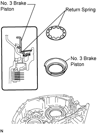
| 7. INSTALL NO. 3 BRAKE PISTON |
Coat the contact surface of the transaxle case with ATF.
Coat the lip seal of the No. 3 brake piston with ATF.
Temporarily install the pawl stopper plate to the transaxle case with the 2 bolts.
Press the return spring installation surface to install the No. 3 brake piston to the transaxle case.
- NOTICE:
- Make sure that the lip of the No. 3 brake piston is not twisted and does not get caught in the transaxle case.
- After installing, make sure that the protrusions on the No. 3 brake piston and the grooves on the pawl stopper plate are aligned.
Install the return spring to the transaxle case.
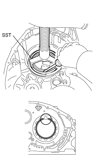
Remove the 2 bolts and pawl stopper plate from the transaxle case.
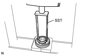
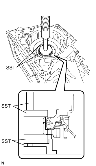
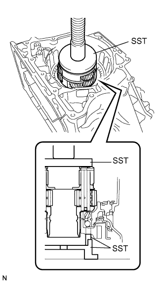
Place SST on the brake piston return spring and compress the brake piston return spring with a press.
- SST
- 09387-00070
- NOTICE:
- Stop the press when the brake piston return spring is flush with the snap ring groove. This prevents the brake piston return spring from being deformed.
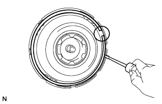
Using a screwdriver, install the snap ring to the transaxle case as shown in the illustration.
- NOTICE:
- Confirm that the snap ring is secured in the groove of the transaxle case.
- Be sure to align the opening ends of the snap ring with the protrusions on the brake piston return spring as shown in the illustration.
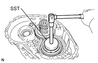
| 8. INSTALL COUNTER DRIVE GEAR |
Using SST and a press, install the bearing inner race (front side) to the counter drive gear.
- SST
- 09387-00020
Install the bearing inner race (rear side) and counter drive gear to the transaxle case.
- SST
- 09223-15030
09527-17011
09950-60020(09951-00810)
09950-70010(09951-07100)
- NOTICE:
- There should not be any clearance between the bearing inner race (front side) and counter drive gear.
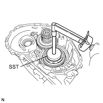
| 9. INSTALL FRONT PLANETARY GEAR ASSEMBLY |
Using SST and a press, press in the planetary gear assembly to the transaxle case.
- SST
- 09223-15030
09527-17011
09951-01100
| 10. INSTALL NO. 2 BRAKE PISTON |
Coat 2 new O-rings with ATF and install them to the No. 2 brake piston.
- NOTICE:
- Ensure that the 2 O-rings are not twisted.
Install the No. 2 brake piston to the transaxle case.
- NOTICE:
- Be careful not to damage the O-rings.
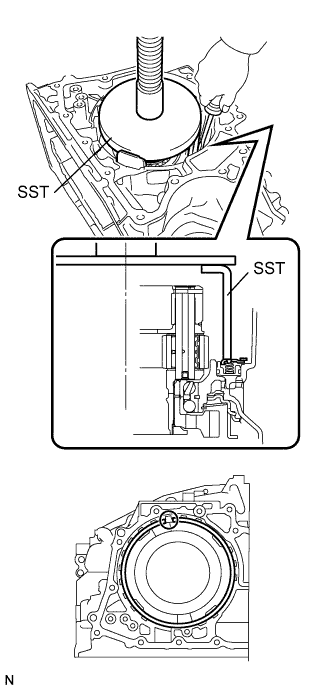
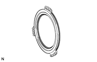
| 11. INSTALL 1ST AND REVERSE BRAKE RETURN SPRING SUB-ASSEMBLY |
Install the 1st and reverse brake return spring to the transaxle case.
Place SST on the 1st and reverse brake return spring and compress the 1st and reverse brake return spring with a press.
- SST
- 09387-00060
- NOTICE:
- Stop the press when the 1st and reverse brake return spring is flush with the snap ring groove. This prevents the 1st and reverse brake return spring from being deformed.
Using a screwdriver, install the snap ring to the transaxle case as shown in the illustration.
- NOTICE:
- Confirm that the snap ring is secured in the groove of the transaxle case.
- Be sure to align the opening ends of the snap ring with the protrusions on the transaxle case as shown in the illustration.
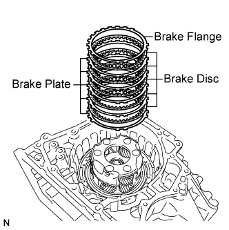
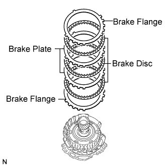
| 12. INSTALL NO. 2 BRAKE DISC |
Install the 5 brake discs, 5 brake plates, and brake flange to the transaxle case.
- NOTICE:
- Make sure that the discs, plates, and flange are installed in the correct order.
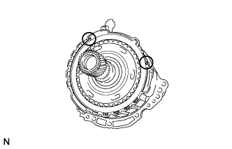
Using a screwdriver, install the snap ring to the transaxle case.
- NOTICE:
- Confirm that the snap ring is secured in the groove of the transaxle case.
- Be sure to align the opening ends of the snap ring with the protrusions on the transaxle case as shown in the illustration.
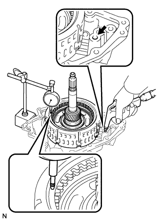
| 13. INSPECT CLEARANCE OF NO. 2 BRAKE |
Using a dial indicator, measure the clearance of the No. 2 brake while applying compressed air (200 kPa, 2.0 kgf/cm2, 29 psi).
- Standard clearance:
- 0.884 to 1.196 mm (0.0348 to 0.0471 in.)
- HINT:
- Measure the clearance at 3 points where the brake piston diameter is approximately 140 mm (5.51 in.) and calculate the average.
If the clearance is not as specified, select an appropriate No. 2 brake flange so that the clearance will be within the specified range.
- HINT:
- There are 5 different thicknesses of flanges available.
No. 2 brake flange thickness: mm (in)Thickness
| Thickness
|
4.0 (0.157)
| 4.3 (0.169)
|
4.1 (0.161)
| 4.4 (0.173)
|
4.2 (0.165)
| -
|
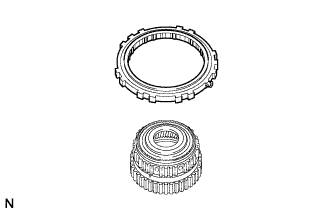
| 14. INSTALL PLANETARY RING GEAR FLANGE |
Install the planetary ring gear flange to the planetary ring gear.
Using a screwdriver, install the snap ring to the planetary ring gear.
- NOTICE:
- Confirm that the snap ring is secured in the groove of the planetary ring gear.
| 15. INSTALL PLANETARY RING GEAR |
Install the planetary ring gear to the one-way clutch assembly.
- NOTICE:
- Make sure that the one-way clutch assembly is positioned in the correct direction as shown in the illustration.
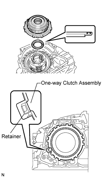
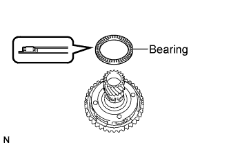
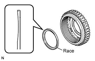
| 16. INSTALL ONE-WAY CLUTCH ASSEMBLY |
Coat the thrust needle roller bearing with ATF, and install it onto the planetary gear assembly.
Bearing diameter: mm (in.)-
| Inside
| Outside
|
Bearing
| 56.1 (2.209)
| 80.9 (3.185)
|
- NOTICE:
- Install the thrust needle roller bearing properly so that the temper colored side of the race will be visible.
Install the one-way clutch assembly to the transaxle case.
- NOTICE:
- Make sure that there is no clearance between the retainer and the claw on the one-way clutch assembly. If there is any clearance, the spring of the retainer will be deformed.
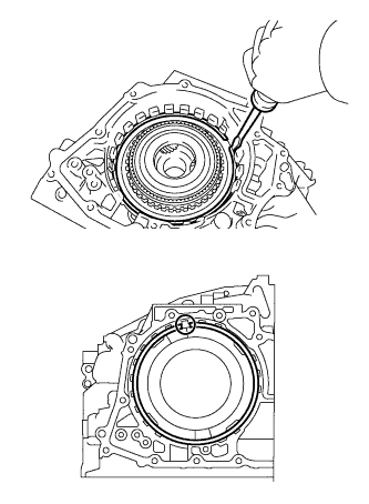
Using a screwdriver, install the snap ring to the transaxle case.
- NOTICE:
- Confirm that the snap ring is secured in the groove of the transaxle case.
- Be sure to align the opening ends of the snap ring with the protrusions on the transaxle case.
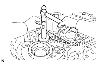
| 17. INSTALL COUNTER DRIVEN GEAR REAR TAPERED ROLLER BEARING OUTER RACE |
Using SST and a hammer, install the counter driven gear rear tapered roller bearing outer race to the transaxle case.
- SST
- 09950-60010(09951-00650)
09950-70010(09951-07100)
- NOTICE:
- Be sure to install the counter driven gear rear tapered roller bearing outer race so that there is no clearance between the bearing outer race and the transaxle case. If there is any clearance, the turning torque of the counter drive gear cannot be measured correctly.
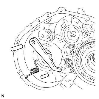
| 18. INSTALL PARKING LOCK PAWL |
Install the parking lock pawl to the transaxle case with the parking lock pawl shaft.
Install the parking lock pawl pin to the transaxle case.
Install the torsion spring to the parking lock pawl.
- NOTICE:
- Make sure that one end of the spring is fixed in the hole of the transaxle case and the other end is positioned on the parking lock pawl as shown in the illustration.
| 19. INSTALL PARKING LOCK SLEEVE |
Install the parking lock sleeve to the transaxle case.
| 20. INSTALL PAWL STOPPER PLATE |
Install the pawl stopper plate to the transaxle case with the 2 bolts.
- Torque:
- 23 N*m{234 kgf*cm, 17 ft.*lbf}
| 21. INSTALL PAWL SHAFT CLAMP |
Install the pawl shaft clamp to the transaxle case with the bolt.
- Torque:
- 23 N*m{234 kgf*cm, 17 ft.*lbf}
| 22. INSTALL COUNTER DRIVEN GEAR FRONT TAPERED ROLLER BEARING |
Using SST and a press, install a new the counter driven gear front tapered roller bearing to the counter driven gear sub-assembly.
- SST
- 09950-60010(09951-00530)
- NOTICE:
- Be sure to install the counter driven gear front tapered roller bearing so that there is no clearance between the bearing and the counter driven gear. If there is any clearance, the turning torque of the counter drive gear cannot be measured correctly.
| 23. INSTALL COUNTER DRIVEN GEAR REAR TAPERED ROLLER BEARING |
Using SST and a press, install a new the counter driven gear rear tapered roller bearing to the counter driven gear sub-assembly.
- SST
- 09950-60010(09951-00420)
- NOTICE:
- Be sure to install the counter driven gear rear tapered roller bearing and the differential drive pinion so that there is no clearance between each of them and the counter driven gear.
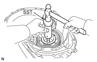
| 24. INSTALL COUNTER DRIVEN GEAR |
Install the counter driven gear sub-assembly to the transaxle case.
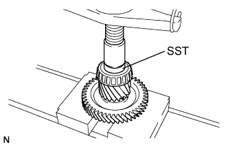
| 25. INSTALL COUNTER DRIVE GEAR NUT |
Turn the manual shaft lever 2 notches counterclockwise to set it in the P position as shown in the illustration.
Using SST, install a new nut.
- SST
- 09387-00130
- Torque:
- 120 N*m{1,223 kgf*cm, 88 ft.*lbf}
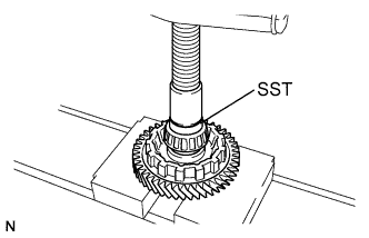
Turn the manual shaft lever 2 notches clockwise to set it in the N position as shown in the illustration.
Using SST and a torque wrench, measure the turning torque of the bearing while rotating SST at 60 rpm.
- SST
- 09387-00130
- Turning torque:
- 0.10 to 0.22 N*m (1.02 to 2.24 kgf*cm, 0.89 to 1.94 in.*lbf)
When the measured value is not within the specified range, gradually tighten the nut until the turning toque falls within the specified range.
- Maximum torque:
- 180 N*m (1,835 kgf*cm, 132 ft.*lbf)
Using SST and a hammer, stake the planetary gear assembly.
- SST
- 09930-00010
| 26. INSTALL FRONT DIFFERENTIAL CASE |
Install the differential case sub-assembly to the transaxle case.
| 27. INSPECT DIFFERENTIAL SIDE GEAR |
Hold the differential case in a vise between aluminum plates.
- NOTICE:
- Do not overtighten the vise.
Place a dial indicator on the tip of the side gear tooth at a right angle.
Hold the pinion gear in the differential case and measure the backlash of the side gear.
- Standard backlash:
- 0 to 0.15 mm (0 to 0.0059 in.)
Thrust washer thicknessThickness
| Thickness
|
1.50 mm (0.0591 in.)
| 1.75 mm (0.0689 in.)
|
1.55 mm (0.0610 in.)
| 1.80 mm (0.0709 in.)
|
1.60 mm (0.0630 in.)
| 1.85 mm (0.07283 in.)
|
1.65 mm (0.0650 in.)
| 1.90 mm (0.07480 in.)
|
1.70 mm (0.0669 in.)
| -
|
If the backlash is greater than the standard range, select another side gear thrust washer.
| 28. INSTALL NO. 1 BRAKE PISTON |
Coat 2 new O-rings with ATF and install them to the No. 1 brake piston.
- NOTICE:
- Ensure that the 2 O-rings are not twisted.
Install the No. 1 brake piston to the oil pump assembly.
- NOTICE:
- Be careful not to damage the O-rings.
| 29. INSTALL 2ND BRAKE PISTON RETURN SPRING SUB-ASSEMBLY |
Install the 3 2nd brake piston return springs to the oil pump assembly.
- NOTICE:
- Make sure that the 3 2nd brake piston return springs are installed straight through the protrusions on the oil pump assembly.
| 30. INSTALL NO. 1 BRAKE DISC |
Install the 4 brake discs, 4 brake plates, and brake flange to the oil pump assembly.
- NOTICE:
- Make sure that the discs, plates, and flange are installed in the correct order.
- Be sure to install the flange in the correct direction.
Place SST on the flange and compress the flange with a press.
- SST
- 09387-00070
09495-65040
- NOTICE:
- Stop the press when the brake piston return spring is flush with the snap ring groove. This prevents the brake piston return spring from being deformed.
Using a screwdriver, install the snap ring to the oil pump assembly as shown in the illustration (#1).
- NOTICE:
- Confirm the snap ring is fixed in the groove of the oil pump assembly.
- Be sure to align the opening ends of the snap ring with the protrusions on the oil pump assembly as shown in the illustration.
Using a screwdriver, install the snap ring to the oil pump assembly as shown in the illustration (#2).
- NOTICE:
- Confirm that the snap ring is secured in the groove of the oil pump assembly.
- Be sure to align the opening ends of the snap ring with the protrusions on the oil pump assembly as shown in the illustration.
| 31. INSPECT CLEARANCE OF NO. 1 BRAKE |
Using a dial indicator, measure the clearance of the No. 1 brake while applying compressed air (200 kPa, 2.0 kgf/cm2, 29 psi).
- Standard clearance:
- 0.807 to 0.974 mm (0.0318 to 0.0383 in.)
- HINT:
- Measure the clearance at 3 points where the brake piston diameter is approximately 140 mm (5.51 in.) and calculate the average.
If the clearance is not as specified, select an appropriate No. 1 brake flange so that the clearance will be within the specified range.
- HINT:
- There are 6 different thicknesses of flanges available.
No. 1 brake flange thickness: mm (in.)Thickness
| Thickness
|
3.0 (0.118)
| 3.3 (0.130)
|
3.1 (0.122)
| 3.4 (0.134)
|
3.2 (0.126)
| 3.5 (0.138)
|
| 32. INSTALL UNDERDRIVE PLANETARY SUN GEAR |
Coat the thrust needle roller bearing with ATF, and install it to the oil pump assembly.
Bearing diameter: mm (in.)-
| Inside
| Outside
|
Bearing
| 57.7 (2.272)
| 75.2 (2.961)
|
- NOTICE:
- Install the thrust needle roller bearing properly so that the temper colored side of the race will be visible.
Install the underdrive planetary sun gear to the oil pump assembly.
| 33. INSTALL INPUT SHAFT SUB-ASSEMBLY |
Coat the 3 input shaft oil seal rings with ATF and install them to the input shaft.
- NOTICE:
- Do not expand the gap of the oil seal ring too much.
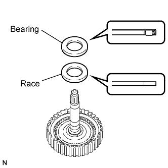
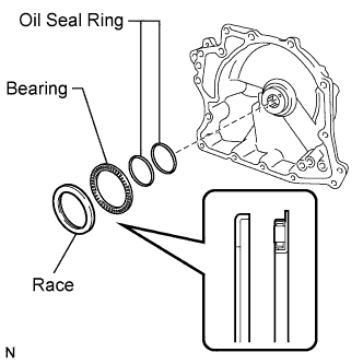
Coat the thrust needle roller bearing and thrust needle roller race with ATF, and install them on the oil pump assembly.
Bearing diameter: mm (in.)-
| Inside
| Outside
|
Bearing
| 29.1 (1.146)
| 48.6 (1.913)
|
Race
| 30.7 (1.209)
| 48.3 (1.902)
|
- NOTICE:
- Be sure to install the thrust needle roller bearing in the correct direction.
Install the input shaft to the oil pump assembly.
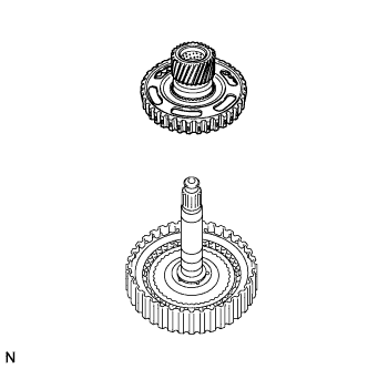
| 34. INSTALL PLANETARY SUN GEAR SUB-ASSEMBLY |
Using a snap ring expander, install the snap ring to the underdrive planetary gear assembly.
Using a snap ring expander, install the front planetary sun gear sub-assembly to the underdrive planetary gear assembly with the snap ring expanded.
| 35. INSTALL UNDERDRIVE PLANETARY RING GEAR |
Install the underdrive planetary ring gear to the underdrive planetary gear assembly.
Using needle-nose pliers, install the snap ring to the underdrive planetary ring gear.
- NOTICE:
- Confirm that the snap ring is secured in the groove of the underdrive planetary ring gear.
| 36. INSTALL NO. 3 BRAKE HUB |
Coat the thrust needle roller bearing with ATF and install it on the underdrive planetary gear assembly.
Bearing diameter: mm (in.)-
| Inside
| Outside
|
Bearing
| 62.6 (2.464)
| 82.9 (3.263)
|
Race
| 65.9 (2.594)
| 80.3 (3.161)
|
- NOTICE:
- Install the thrust needle roller bearing properly so that the temper colored side of the race will be visible.
Coat the race with MP grease and install it to the No. 3 brake hub.
Install the No. 3 brake hub to the underdrive planetary gear assembly.
| 37. INSTALL UNDERDRIVE PLANETARY GEAR ASSEMBLY |
Install the underdrive planetary gear assembly to the oil pump assembly.
| 38. INSTALL NO. 3 BRAKE DISC |
Install the 2 brake flanges, 3 brake discs, and 2 brake plates to the oil pump assembly.
- NOTICE:
- Make sure that the discs, plates, and flange are installed in the correct order.
Using a screwdriver, install the snap ring to the oil pump assembly.
- NOTICE:
- Confirm the snap ring is fixed in the groove of the oil pump.
- Be sure to align the opening ends of the snap ring with the protrusions on the brake piston return spring as shown in the illustration.
| 39. INSPECT CLEARANCE OF NO. 3 BRAKE |
| 40. INSTALL FRONT OIL PUMP AND GEAR BODY SUB-ASSEMBLY |
Coat the O-ring with ATF and install it to the transaxle case.
Coat the thrust needle roller bearing and thrust needle roller race with ATF and install them on the underdrive planetary gear assembly.
Bearing and race diameter: mm (in.)-
| Inside
| Outside
|
Bearing
| 53.1 (2.091)
| 79 (3.11)
|
Race
| 59.4 (2.339)
| 77 (3.03)
|
- NOTICE:
- Install the thrust needle roller bearing properly so that the temper colored side of the race will be visible.
Coat the O-ring with ATF and install it to the oil pump.
Install the oil pump assembly to the transaxle case with the 7 bolts.
- Torque:
- 23 N*m{234 kgf*cm, 17 ft.*lbf}
| 41. INSTALL DIFFERENTIAL GEAR LUBE APPLY TUBE |
Install the differential gear lube apply tube to the transaxle housing.
- NOTICE:
- Insert the differential lube apply tube into the transaxle case until it makes contact with the stopper.
Install the apply tube clamp to the differential gear lube apply tube with the bolt.
- Torque:
- 23 N*m{234 kgf*cm, 17 ft.*lbf}
- NOTICE:
- There should be clearance between the differential lube apply tube and apply tube clamp.
| 42. INSTALL COUNTER DRIVEN GEAR FRONT TAPERED ROLLER BEARING OUTER RACE |
Install the shim to the transaxle housing.
Using SST, install a new counter driven gear front tapered roller bearing outer race to the transaxle housing.
- SST
- 09950-60020(09951-00810)
09950-70010(09951-07100)
- NOTICE:
- Be sure to install the counter driven gear front tapered roller bearing outer race so that there is no clearance between the shim and the transaxle housing.
| 43. INSTALL TRANSAXLE HOUSING |
Remove packing material from the contact surface between the transaxle housing and case.
- NOTICE:
- Make sure that there is no ATF on the contact surface.
Apply FIPG to the transaxle case.
- FIPG:
- Toyota Genuine Seal Packing 1281, Three Bond 1281 or equivalent.
- NOTICE:
- Apply a bead of FIPG (width 1.2 mm (0.047 in.)) along the sealing surface.
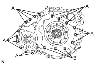
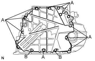
Install the transaxle housing to the transaxle case with the 20 bolts.
- Torque:
- Bolt A:
- 31 N*m{316 kgf*cm, 23 ft.*lbf}
- Bolt B:
- 23 N*m{234 kgf*cm, 17 ft.*lbf}
| 44. ADJUST COUNTER DRIVEN GEAR PRELOAD |
|
Using SST and a torque wrench, measure the turning torque of the counter driven gear while rotating SST at 10 rpm.
- SST
- 09564-33010
- Turning torque:
- Differential side bearing preload 3.29 to 6.07 N*m (33.53 to 61.86 kgf*cm, 2.42 to 4.46 ft.*lbf)
If the turning torque is not within the specified range, refer to the table below to select a shim of the counter driven gear front tapered roller bearing outer race so that the turning torque is within the specified range.
Thickness
| Thickness
| Thickness
| Thickness
|
2.000 (0.0787)
| 2.275 (0.0896)
| 2.525 (0.0994)
| 2.775 (0.1093)
|
2.025 (0.0797)
| 2.300 (0.0906)
| 2.550 (0.1004)
| 2.800 (0.1102)
|
2.050 (0.0807)
| 2.325 (0.0915)
| 2.575 (0.1014)
| 2.825 (0.1112)
|
2.075 (0.0817)
| 2.350 (0.0925)
| 2.600 (0.1024)
| 2.850 (0.1122)
|
2.100 (0.0827)
| 2.375 (0.0935)
| 2.625 (0.1034)
| 2.875 (0.1132)
|
2.125 (0.0837)
| 2.400 (0.0945)
| 2.650 (0.1043)
| 2.900 (0.1142)
|
2.150 (0.0847)
| 2.425 (0.0955)
| 2.675 (0.1053)
| 2.925 (0.1152)
|
2.175 (0.0856)
| 2.450 (0.0965)
| 2.700 (0.1063)
| 2.950 (0.1161)
|
2.200 (0.0866)
| 2.475 (0.0974)
| 2.725 (0.1073)
| 2.975 (0.1171)
|
2.225 (0.0876)
| 2.500 (0.0984)
| 2.750 (0.1083)
| 3.000 (0.1181)
|
2.250 (0.0886)
| -
| -
| -
|
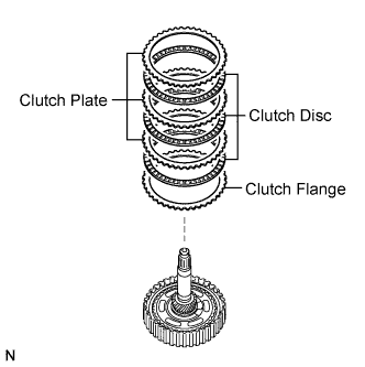
| 45. INSTALL NO. 1 CLUTCH DISC |
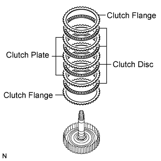
Install the clutch flange, 4 clutch discs, and 4 clutch plates to the direct multiple disc clutch assembly.
- NOTICE:
- Make sure that the flange, discs, and plates are installed in the correct order.
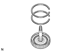
Using a screwdriver, install the 2 snap rings to the direct multiple disc clutch assembly.
- NOTICE:
- Confirm that the snap ring is secured in the groove of the direct multiple disc clutch assembly.
| 46. INSPECT CLEARANCE OF NO. 1 CLUTCH DISC |
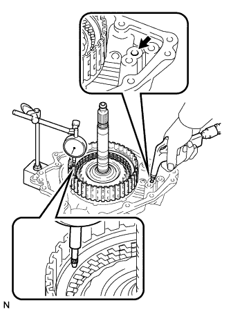
Install the direct multiple disc clutch assembly onto the transaxle rear cover.
Using a dial indicator, measure the No. 1 clutch pack clearance while applying and releasing compressed air (200 kPa, 2.0 kgf/cm2, 29 psi).
- HINT:
- Measure the clearance at 3 points where the flange diameter is approximately 152 mm (5.98 in.) and calculate the average.
- Pack clearance:
- 0.806 to 0.974 mm (0.0317 to 0.0383 in.)
If the pack clearance is not as specified, inspect the discs, plates and flange.
- HINT:
- There are 6 different thicknesses of flanges available.
No. 1 clutch flange thickness: mm (in.)Thickness
| Thickness
|
3.0 (0.118)
| 3.3 (0.130)
|
3.1 (0.122)
| 3.4 (0.134)
|
3.2 (0.126)
| 3.5 (0.138)
|
| 47. INSTALL REAR PLANETARY SUN GEAR ASSEMBLY |
Coat the thrust needle roller bearing and thrust needle roller race with ATF, and install them to the direct multiple disc clutch assembly.
Bearing and race diameter: mm (in.)-
| Inside
| Outside
|
Bearing
| 28 (1.10)
| 47.1 (1.854)
|
Race
| 26.1 (1.028)
| 44 (1.73)
|
- NOTICE:
- Install the thrust needle roller bearing properly so that the temper colored side of the race will be visible.
Install the rear planetary sun gear to the direct multiple disc clutch assembly.
Using a snap ring expander, install the snap ring to the direct multiple disc clutch assembly.
| 48. INSTALL NO. 2 CLUTCH DISC |
Install the clutch flange, 3 clutch discs, and 3 clutch plates to the direct multiple disc clutch assembly.
- NOTICE:
- Make sure that the flange, discs, and plates are installed in the correct order.
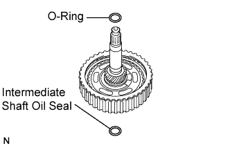
| 49. INSTALL DIRECT MULTIPLE DISC CLUTCH SNAP RING |
Coat a new O-ring with ATF and install it to the direct multiple disc clutch assembly.
Coat a new intermediate shaft oil seal ring with ATF and install it to the intermediate shaft.
Install the No. 2 direct clutch piston to the direct multiple disc clutch assembly.
- NOTICE:
- Be sure to engage the claws on the direct multiple disc clutch assembly to the grooves on the No. 2 direct clutch piston.
Using a screwdriver, install the snap ring to the direct multiple disc clutch assembly.
- NOTICE:
- Position the opening of the snap ring as shown in the illustration.
| 50. INSPECT CLEARANCE OF NO. 2 CLUTCH DISC |
Install the direct multiple disc clutch assembly onto the transaxle rear cover.
Using a dial indicator, measure the No. 2 clutch pack clearance while applying and releasing compressed air (200 kPa, 2.0 kgf/cm2, 29 psi).
- HINT:
- Measure the clearance at 3 points where the diameter of the No. 2 direct multiple clutch piston is approximately 152 mm (5.98 in.) and calculate the average.
- Pack clearance:
- 0.544 to 0.744 mm (0.0214 to 0.0293 in.)
If the pack clearance is not as specified, inspect the discs, plates and flange.
- HINT:
- There are 6 different thicknesses of flanges available.
No. 2 clutch flange thickness: mm (in.)Thickness
| Thickness
|
3.0 (0.118)
| 3.3 (0.130)
|
3.1 (0.122)
| 3.4 (0.134)
|
3.2 (0.126)
| 3.5 (0.138)
|
| 51. INSTALL REAR MULTIPLE DISC CLUTCH ASSEMBLY |
Coat the thrust needle roller bearing with ATF and install it on the transaxle case.
Bearing diameter: mm (in.)-
| Inside
| Outside
|
Bearing
| 61.2 (2.409)
| 79 (3.11)
|
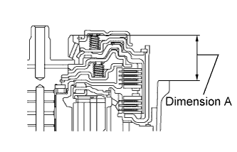
Install the direct multiple disc clutch assembly to the transaxle case.
Clean the contact surface of the transaxle case and transaxle rear cover.
As shown in the illustration, place a straight edge on the multiple direct clutch drum and measure the distance between the transaxle case and the straight edge using vernier calipers (Dimension A).
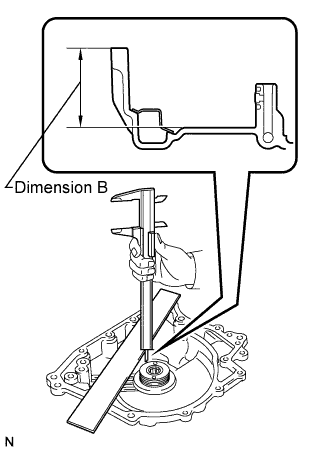
Using vernier calipers and a straight edge, measure the distance shown in the illustration. (Dimension B)
Calculate the end play value using the following formula:
End play = Dimension B - Dimension A
- End play:
- 0.007 to 1.113 mm (0.0003 to 0.0438 in.)
| 52. INSTALL TRANSAXLE REAR COVER SUB-ASSEMBLY |
Using SST and a hammer, install the needle roller bearing into the transaxle rear cover.
- SST
- 09950-60010(09951-00220)
09950-70010(09951-07100)
- Press installation depth:
- 21.5 to 21.9 mm (0.8464 to 08622 in.)
Apply adhesive or equivalent to the 2 "TORX" screws.
- Adhesive:
- Toyota Genuine Adhesive 1324, Three Bond 1324 or equivalent
Using a "TORX" wrench (T30), install the transaxle rear cover plate to the transaxle rear cover with the 2 "TORX" screws.
- Torque:
- 7.5 N*m{76 kgf*cm, 66 in.*lbf}
- NOTICE:
- Apply adhesive to the screws and install them within 10 minutes of adhesive application.
Coat the thrust needle roller bearing and thrust needle roller race with ATF and install it on the transaxle case.
Bearing diameter: mm (in.)-
| Inside
| Outside
|
Bearing
| 48.9 (1.925)
| 72.0 (2.835)
|
Race
| 52.2 (2.055)
| 70.4 (2.772)
|
Coat the 2 new oil seals with ATF and install them to the transaxle rear cover.
Coat the 3 O-rings with ATF and install them to the transaxle case.
- NOTICE:
- Ensure that the 3 O-rings are not twisted.
Remove packing material from the contact surfaces between the transaxle rear cover and transaxle case.
- NOTICE:
- Make sure that there is no ATF on the contact surface.
- FIPG:
- Toyota Genuine Seal Packing 1281, Three Bond 1281 or equivalent.
Install the transaxle rear cover to the transaxle case with the 14 bolts.
- Torque:
- Bolt A:
- 23 N*m{234 kgf*cm, 17 ft.*lbf}
- Bolt B:
- 17 N*m{173 kgf*cm, 12 ft.*lbf}
Install a new gasket to the refill plug.
Install the refill plug to the transaxle rear cover.
- Torque:
- 49 N*m{500 kgf*cm, 36 ft.*lbf}
Coat 2 new O-rings with ATF and install them to the 2 No. 1 automatic transaxle case plugs.
Install the 2 No. 1 automatic transaxle case plugs to the transaxle rear cover.
- Torque:
- 7.4 N*m{75 kgf*cm, 65 in.*lbf}
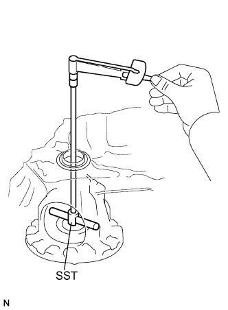
| 53. INSPECT INPUT SHAFT END PLAY |
Using a dial indicator, measure the input shaft end play.
- End play:
- 0.012 to 1.250 mm (0.0005 to 0.0492 in.)
| 54. INSTALL TRANSAXLE CASE GASKET |
Coat the 2 gaskets with ATF and install them to the transaxle case.
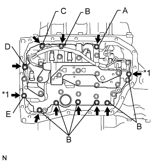
| 55. INSTALL TRANSMISSION VALVE BODY ASSEMBLY |
Install the valve body assembly to the transaxle case with the 11 bolts.
- Torque:
- 11 N*m{112 kgf*cm, 8 ft.*lbf}
-
- | Bolt length
Bolt length |
Bolt A
| 25 mm (0.98 in.)
|
Bolt B
| 30 mm (1.18 in.)
|
Bolt C
| 35 mm (1.38 in.)
|
Bolt D
| 45 mm (1.77 in.)
|
Bolt E
| 55 mm (2.17 in.)
|
- NOTICE:
- When installing the transmission valve body assembly, be careful not to allow the transmission revolution sensor and transaxle case to interfere each other.
- Be sure to insert the pin of the manual valve lever into the groove on the end of the manual valve.
- First, temporarily tighten the bolts marked by (*1) in the illustration because they are positioning bolts.
| 56. INSTALL VALVE BODY OIL STRAINER ASSEMBLY |
Coat a new O-ring with ATF and install it to the oil strainer assembly.
- NOTICE:
- Ensure that the O-ring is not twisted or pinched.
Install the oil strainer assembly to the valve body assembly with the 2 bolts.
- Torque:
- 11 N*m{112 kgf*cm, 8 ft.*lbf}
| 57. INSTALL AUTOMATIC TRANSAXLE OIL PAN SUB-ASSEMBLY |
Install the 2 magnets in the automatic transaxle oil pan sub-assembly.
Apply adhesive or equivalent to the 18 bolts.
- Adhesive:
- Toyota Genuine Adhesive 1344, Three Bond 1344 or equivalent.
Install the automatic transaxle oil pan sub-assembly and a new gasket to the transaxle case with the 18 bolts.
- Torque:
- 7.5 N*m{76 kgf*cm, 66 in.*lbf}
- NOTICE:
- In order to ensure proper sealing of the transmission pan bolts, apply adhesive to the bolts and install them within 10 minutes of adhesive application.
- Completely remove any oil or grease from the contact surface of the transaxle case and oil pan sub-assembly with the gasket before installation.
Install the No. 1 oil filler tube from the automatic transaxle assembly.
Install the overflow plug and a new gasket to the oil pun sub-assembly.
- Torque:
- 40 N*m{408 kgf*cm, 30 ft.*lbf}
| 58. INSTALL NO. 1 TRANSAXLE CASE PLUG |
Install the 3 gaskets to the 3 hexagon bolts.
Apply adhesive or equivalent to the 3 hexagon bolts.
- Adhesive:
- Toyota Genuine adhesive 1344, Three Bond 1344 or equivalent.
- NOTICE:
- In order to ensure proper sealing of the hexagon bolts, apply adhesive to the bolts and install them within 10 minutes of adhesive application.
Install the 3 hexagon bolts to the transaxle housing with the gaskets.
- Torque:
- 29 N*m{296 kgf*cm, 21 ft.*lbf}
Coat 3 new O-rings with the ATF and install them to the 3 No. 1 transaxle case plugs.
Install the 3 No. 1 transaxle case plugs to the transaxle case.
- Torque:
- 7.4 N*m{75 kgf*cm, 65 in.*lbf}
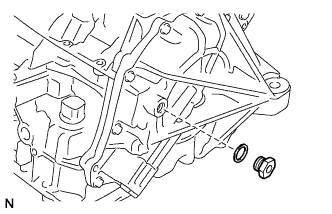
| 59. INSTALL OIL COOLER TUBE UNION (OUTLET OIL COOLER UNION) |
Coat a new O-ring with ATF and install it to the oil cooler tube union (outlet oil cooler union).
Install the oil cooler tube union (outlet oil cooler union) to the transaxle case as shown in the illustration.
- Torque:
- 27 N*m{275 kgf*cm, 20 ft.*lbf}
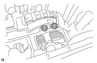
| 60. INSTALL OIL COOLER TUBE UNION (INLET OIL COOLER UNION) |
Coat a new O-ring with ATF and install it to the oil cooler tube union (inlet oil cooler union).
Install the oil cooler tube union (inlet oil cooler union) to the transaxle case.
- Torque:
- 27 N*m{275 kgf*cm, 20 ft.*lbf}
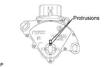
| 61. INSTALL PARK/NEUTRAL POSITION SWITCH ASSEMBLY |
Align the protrusions of the park/neutral position switch.
Install the park/neutral position switch to the control shaft with the 2 bolts.
- Torque:
- 5.4 N*m{55 kgf*cm, 48 in.*lbf}
- NOTICE:
- Before installing the park/neutral position switch, remove any dirt or rust on the installation portion of the control shaft. Be sure to install the switch straight along the shaft while being careful not to deform the plate spring that supports the shaft. If the plate spring is deformed, the park/neutral switch cannot be reinstalled correctly.
- After installing the park/neutral position switch, confirm that the 2 protrusions on the switch are aligned.
Install the control shaft lever to the control shaft with the washer and nut.
- Torque:
- 13 N*m{130 kgf*cm, 9 ft.*lbf}
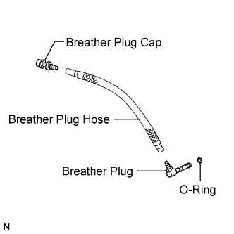
| 62. INSTALL BREATHER PLUG HOSE |
Install a new O-ring to the breather plug.
Install the breather plug to the breather plug hose.
Install the breather plug cap to the breather plug hose.
Install the breather plug hose to the transaxle case.