Differential Oil Seal Installation
INSTALL TRANSAXLE CASE OIL SEAL
INSTALL FRONT TRANSAXLE CASE OIL SEAL
INSTALL FRONT DRIVE SHAFT ASSEMBLY LH
INSTALL FRONT DRIVE SHAFT ASSEMBLY RH
INSTALL FRONT AXLE ASSEMBLY LH
INSTALL FRONT AXLE ASSEMBLY RH
INSTALL FRONT SUSPENSION LOWER NO. 1 ARM LH
INSTALL FRONT SUSPENSION LOWER NO. 1 ARM RH
INSTALL TIE ROD ASSEMBLY LH
INSTALL TIE ROD ASSEMBLY RH
INSTALL FRONT SPEED SENSOR LH
INSTALL FRONT SPEED SENSOR RH
INSTALL FRONT STABILIZER LINK ASSEMBLY LH
INSTALL FRONT STABILIZER LINK ASSEMBLY RH
INSTALL FRONT AXLE HUB NUT LH
INSTALL FRONT AXLE HUB NUT RH
INSTALL FRONT WHEELS
ADD AUTOMATIC TRANSAXLE FLUID
ADJUST FRONT WHEEL ALIGNMENT
CHECK ABS SPEED SENSOR SIGNAL
Differential Oil Seal -- Installation |
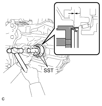
| 1. INSTALL TRANSAXLE CASE OIL SEAL |
Using SST and a hammer, install a new oil seal to the transaxle case.
- SST
- 09316-10010
09950-70010(09951-07100)
- Oil seal installation depth:
- -0.5 to 0.5 mm (-0.020 to 0.020 in.)
Coat the lip of the oil seal with MP grease.
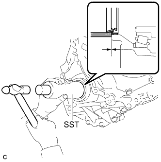
| 2. INSTALL FRONT TRANSAXLE CASE OIL SEAL |
Using SST and a hammer, install a new oil seal to the transaxle housing.
- SST
- 09308-14010
- Oil seal installation depth:
- -0.5 to 0.5 mm (-0.020 to 0.020 in.)
Coat the lip of the oil seal with MP grease.
| 3. INSTALL FRONT DRIVE SHAFT ASSEMBLY LH |
Coat the spline of the inboard joint shaft assembly with ATF.
Align the shaft splines and install the drive shaft assembly LH with a brass bar and hammer.
- NOTICE:
- Set the shaft snap ring with the opening side facing down.
- Be careful not to damage the drive shaft dust cover, boot, and oil seal.
- Move the drive shaft assembly while keeping it level.
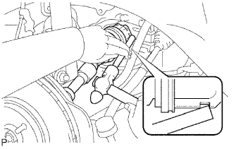
| 4. INSTALL FRONT DRIVE SHAFT ASSEMBLY RH |
Coat the spline of the inboard joint shaft assembly with ATF.
Install the front drive shaft the assembly RH.
Using a screwdriver, install a new bearing bracket hole snap ring.
- NOTICE:
- Do not damage the boot and oil seal.
- Move the drive shaft assembly while keeping it level.
Install a new bolt.
- Torque:
- 32 N*m{330 kgf*cm, 24 ft.*lbf}
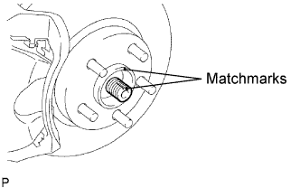
| 5. INSTALL FRONT AXLE ASSEMBLY LH |
Align the matchmarks and install the front drive shaft assembly to the front axle hub sub-assembly.
- NOTICE:
- Be careful not to damage the drive shaft boot and speed sensor rotor.
| 6. INSTALL FRONT AXLE ASSEMBLY RH |
- HINT:
- Use the same procedures described for the LH side.
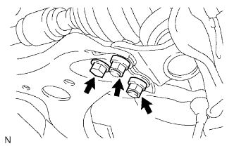
| 7. INSTALL FRONT SUSPENSION LOWER NO. 1 ARM LH |
Install the lower ball joint to the front suspension lower No. 1 arm with the bolt and 2 nuts.
- Torque:
- 75 N*m{765 kgf*cm, 55 ft.*lbf}
| 8. INSTALL FRONT SUSPENSION LOWER NO. 1 ARM RH |
- HINT:
- Use the same procedures described for the LH side.
| 9. INSTALL TIE ROD ASSEMBLY LH |
Install the tie rod end sub-assembly to the steering knuckle with the nut.
- Torque:
- 49 N*m{500 kgf*cm, 36 ft.*lbf}
Install a new cotter pin.
- NOTICE:
- If the holes for the cotter pin are not aligned, tighten the nut up to 60° further.
| 10. INSTALL TIE ROD ASSEMBLY RH |
- HINT:
- Use the same procedures described for the LH side.
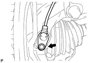
| 11. INSTALL FRONT SPEED SENSOR LH |
Install the front speed sensor to the steering knuckle with the bolt.
- Torque:
- 8.0 N*m{82 kgf*cm, 71 in.*lbf}
- NOTICE:
- Prevent foreign matter from adhering to the speed sensor.
- Be careful not to damage the speed sensor.
Install the flexible hose and the speed sensor to the shock absorber with the bolt and set the sensor clip on the knuckle.
- Torque:
- 19 N*m{192 kgf*cm, 14 ft.*lbf}
- NOTICE:
- Be careful not to damage the speed sensor.
- Prevent foreign matter from adhering to the speed sensor.
- Do not twist the sensor wire when installing the speed sensor.
| 12. INSTALL FRONT SPEED SENSOR RH |
- HINT:
- Use the same procedures described for the LH side.
| 13. INSTALL FRONT STABILIZER LINK ASSEMBLY LH |
Install the stabilizer link assembly with the nut.
- Torque:
- 74 N*m{755 kgf*cm, 55 ft.*lbf}
- HINT:
- If the ball joint turns together with the nut, use a hexagon wrench (6 mm) to hold the stud.
| 14. INSTALL FRONT STABILIZER LINK ASSEMBLY RH |
- HINT:
- Use the same procedures described for the LH side.
| 15. INSTALL FRONT AXLE HUB NUT LH |
Clean the threaded parts on the drive shaft and front axle hub nut using a non-residue solvent.
- NOTICE:
- Be sure to perform this work for a new drive shaft. Keep the threaded parts free of oil and foreign objects.
Using a socket wrench (30 mm), install a new axle hub nut.
- Torque:
- 294 N*m{3,000 kgf*cm, 217 ft.*lbf}
Using a chisel and hammer, stake the front axle hub nut.
| 16. INSTALL FRONT AXLE HUB NUT RH |
- HINT:
- Use the same procedures described for the LH side.
- Torque:
- 103 N*m{1,050 kgf*cm, 76 ft.*lbf}
| 18. ADD AUTOMATIC TRANSAXLE FLUID |
- HINT:
- (CAMRY_ACV40 RM0000013BU00VX.html)
| 19. ADJUST FRONT WHEEL ALIGNMENT |
- HINT:
- (CAMRY_ACV40 RM0000011DA015X.html)
| 20. CHECK ABS SPEED SENSOR SIGNAL |
ABS: (CAMRY_ACV40 RM000001JBD011X.html)
VSC: (CAMRY_ACV40 RM000000XHT028X.html)