INSPECT SPEED SENSOR (SENSOR INSTALLATION)
CHECK IF DTC OUTPUT RECURS (SEE IF DTC P0715 AND/OR P0717 IS OUTPUT AGAIN)
DTC P0715 Input / Turbine Speed Sensor Circuit Malfunction |
DTC P0717 Input Speed Sensor Circuit No Signal |
SYSTEM DESCRIPTION
This sensor detects the rotation speed of the turbine which shows the input revolution of transaxle. By comparing the input turbine speed signal (NT) with the counter gear speed sensor signal (NC), the TCM detects the shift timing of the gears and appropriately controls the engine torque and hydraulic pressure according to various conditions, thus, providing smooth gear shift.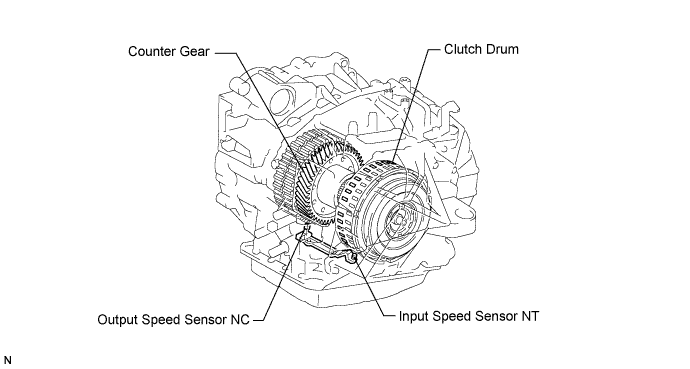
| DTC No. | DTC Detection Condition | Trouble Area |
| P0715 | When the speed sensor input voltage is either more than 1.9 V or less than 0.1 V for 4.5 seconds or more. |
|
| P0717 | ECM detects conditions (a), (b) and (c) continuously for 5 sec. or more (1-trip detection logic): (a) Vehicle speed: 31 mph (50 km/h) or more. (b) Park/neutral position switch (STAR and R) is OFF. (c) Speed sensor (NT): less than 300 rpm. |
MONITOR DESCRIPTION
The NT terminal of the TCM detects a revolution signal from the speed sensor (NT) (input RPM). The TCM calculates a gearshift comparing the speed sensor (NT) with the speed sensor (NC).While the vehicle is operating in 2nd, 3rd, 4th or 5th gear in the shift position of D, if the input shaft revolution is less than 300 rpm *1although the output shaft revolution is more than 1,000 rpm *2, the TCM interprets this as a fault, illuminates the MIL and stores the DTC.
*1: Pulse is not output or is irregularly output.
*2: The vehicle speed is 50 km/h (31 mph) or more.
WIRING DIAGRAM

INSPECTION PROCEDURE
| DATA LIST |
- NOTICE:
- In the table below, the values listed under "Normal Condition" are reference values. Do not depend solely on these reference values when deciding whether a part is faulty.
- HINT:
- According to the Data List displayed on the intelligent tester, you can read the value of switches, sensors, actuators and other items without removing any parts. Reading the Data List as the first step in troubleshooting is one method to save labor time.
Warm up the engine.
Turn the ignition switch off.
Connect the intelligent tester to the DLC3.
Turn the ignition switch on.
Turn on the tester.
Enter the following items: "Powertrain / ECT / Data List".
According to the display on the tester, read "Data List".
Item Measurement Item/ Range (display) Normal Condition SPD (NT) Input Turbine Speed / display: 50 r/min - HINT:
- Lock-up ON (after warming up the engine); input turbine speed (NT) is equal to the engine speed.
- Lock-up OFF (idling at N position); input turbine speed (NT) is nearly equal to the engine speed.
- HINT:
- SPD (NT) is always 0 while driving: Open or short in the sensor or circuit.
- SPD (NT) is always more than 0 and less than 300 rpm while driving the vehicle at 50 km/h (31 mph) or more: Sensor trouble, improper installation, or intermittent connection trouble of the circuit.
| 1.INSPECT SPEED SENSOR (SENSOR INSTALLATION) |
Make sure that the connector is properly connected, and check the speed sensor installation.
- OK:
- The installation bolt is tightened properly and there is no clearance between the sensor and transaxle case.
 |
|
| ||||
| OK | |
| 2.CHECK TRANSMISSION WIRE |
Remove the TCM.
 |
Disconnect the speed sensor connector from the transmission wire.
Measure the resistance according to the value(s) in the table below.
- Standard resistance:
Tester Condition Specified Condition NTO - NTO Below 1 Ω NTB - NTB Below 1 Ω NTO - NTB 10 kΩ or higher
|
| ||||
| OK | |
| 3.REPLACE SPEED SENSOR |
| NEXT | |
| 4.CHECK IF DTC OUTPUT RECURS (SEE IF DTC P0715 AND/OR P0717 IS OUTPUT AGAIN) |
Connect the intelligent tester to the DLC3.
Start the engine and turn the intelligent tester main switch ON.
Perform the monitor drive pattern (CAMRY_ACV40 RM000000W7K02CX.html).
When you use intelligent tester:
Select the item "Powertrain / ECT / DTC / Current or Pending".
Read the DTCs using the intelligent tester.
- Result:
Display (DTC output) Proceed to Only "P0715 or P0717" is output A No output B
|
| ||||
| A | ||
| ||