Dtc P0989 Transmission Fluid Pressure Sensor / Switch E Circuit Low
DESCRIPTION
MONITOR DESCRIPTION
WIRING DIAGRAM
INSPECTION PROCEDURE
CHECK OTHER DTC OUTPUT (IN ADDITION TO DTC P0989 OR P0990)
CHECK TRANSMISSION WIRE (SHORT TO GROUND)
CHECK ATF TEMPERATURE SENSOR ASSEMBLY (ATF PRESSURE SWITCH NO.3)
CHECK TRANSMISSION WIRE
DTC P0989 Transmission Fluid Pressure Sensor / Switch "E" Circuit Low |
DTC P0990 Transmission Fluid Pressure Sensor / Switch "E" Circuit High |
DESCRIPTION
ATF pressure switch No. 3 is installed in the lockup solenoid ATF output passage and is used to detect a malfunction in the lockup solenoid.DTC No.
| DTC Detection Condition
| Trouble Area
|
P0989
| Transmission fluid pressure switch No. 3 is OFF when lock-up occurs in response to a lock-up request (2 trip detection logic).
| - ATF temperature sensor assembly (ATF pressure switch No. 3)
- Transmission wire
- TCM
|
P0990
| When both of the following are detected (2 trip detection logic):
- Transmission fluid pressure switch No. 3 is ON when lock-up does not occur.
- Lock-up does not occur when shift solenoid valve (SLU) is requested to turn off in the lock-up range.
|
MONITOR DESCRIPTION
The TCM illuminates the MIL and stores the DTC when the TCM detects that the ATF pressure switch is OFF with the lock-up solenoid ON or when the TCM detects that the ATF pressure switch is ON with the lock-up solenoid OFF.
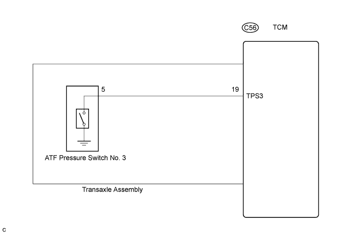
WIRING DIAGRAM
INSPECTION PROCEDURE
| 1.CHECK OTHER DTC OUTPUT (IN ADDITION TO DTC P0989 OR P0990) |
Connect the intelligent tester to the DLC3.
Turn the ignition switch on and turn the intelligent tester on.
Enter the following items: "Powertrain / ECT / DTC / Current or Pending".
Read the DTCs using the intelligent tester.
- Result:
Display (DTC output)
| Proceed to
|
Only "P0990" is output
| A
|
Only "P0989" is output
| B
|
"P0989 or P0990" and other DTCs
| C
|
- HINT:
- If a solenoid is stuck OFF, DTCs for several solenoids including the malfunctioning solenoid will be detected.
| 2.CHECK TRANSMISSION WIRE (SHORT TO GROUND) |
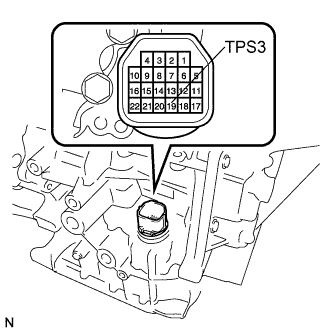
Remove the TCM.
Measure the resistance according to the value(s) in the table below.
- Standard resistance:
Tester Condition
| Specified Condition
|
19 (TPS3) - Body ground (Valve body assembly)
| 10 kΩ or higher
|
| 3.CHECK ATF TEMPERATURE SENSOR ASSEMBLY (ATF PRESSURE SWITCH NO.3) |
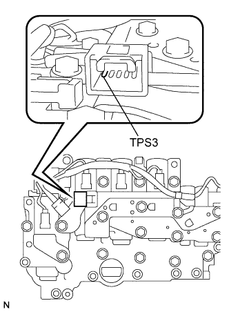
Disconnect the connector from the ATF temperature sensor assembly.
Measure the resistance according to the value(s) in the table below.
- Standard resistance:
Tester Condition
| Specified Condition
|
5 (TPS3) - Body ground (Valve body assembly)
| 10 kΩ or higher
|
| | REPLACE ATF TEMPERATURE SENSOR ASSEMBLY |
|
|
| OK |
|
|
|
| REPLACE TRANSMISSION WIRE |
|
| 4.CHECK TRANSMISSION WIRE |
Remove the TCM.
Disconnect the speed sensor connector from the transmission wire.
Measure the resistance according to the value(s) in the table below.
- Standard resistance:
Tester Condition
| Specified Condition
|
19 (TPS3) - 5 (TPS3)
| Below 1 Ω
|
19 (TPS3) or 5 (TPS3) - Body ground (Valve body assembly)
| 10 kΩ or higher
|
| | REPLACE TRANSMISSION WIRE |
|
|
| OK |
|
|
|
| REPLACE ATF TEMPERATURE SENSOR ASSEMBLY |
|