DESCRIPTION
WIRING DIAGRAM
INSPECTION PROCEDURE
CHECK ENTRY FUNCTION DETECTION AREA
CHECK FOR DTC
CHECK ENGINE SWITCH CONDITION
CHECK CRANKING FUNCTION
READ VALUE USING INTELLIGENT TESTER (P SIGNAL)
READ VALUE USING INTELLIGENT TESTER (STOP LIGHT SWITCH)
READ VALUE USING INTELLIGENT TESTER (STEERING LOCK)
CHECK STEERING LOCK
INSPECT MAIN BODY ECU (STSW VOLTAGE)
INSPECT ECM (ACCR VOLTAGE)
INSPECT ECM (STR2 VOLTAGE)
CHECK WIRE HARNESS (MAIN BODY ECU -ECM - ENGINE ROOM R/B)
INSPECT RELAY (ST CUT)
INSPECT PARK/NEUTRAL POSITION SWITCH
CHECK HARNESS AND CONNECTOR (PARK/NEUTRAL POSITION SWITCH - ECM)
INSPECT RELAY (ST)
CHECK HARNESS AND CONNECTOR (ECM AND STARTER - ST RELAY)
INSPECT ENGINE ROOM RELAY BLOCK (ST RELAY VOLTAGE)
INSPECT STARTER ASSEMBLY
READ VALUE USING INTELLIGENT TESTER (L CODE)
READ VALUE USING INTELLIGENT TESTER (ENGINE START REQUEST)
READ VALUE USING INTELLIGENT TESTER (S CODE)
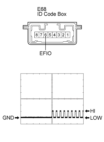
INSPECT ID CODE BOX
ENTRY AND START SYSTEM - Engine does not Start |
DESCRIPTION
| ENGINE START SYSTEM FUNCTION |
If the engine switch is pressed with the shift lever in the P or N position and the brake pedal depressed, the main body ECU determines that it is an engine start request.
The certification ECU and other ECUs perform key verification via the LIN communication line.
The main body ECU activates the ACC relay.
The main body ECU activates the IG1 and IG2 relays.
The certification ECU outputs a steering UNLOCK signal. The signal is sent to the main body ECU via the steering lock ECU.
The main body ECU sends an engine start request signal to the ECM.
The ECM sends an ACC cut request signal to the main body ECU.
The ECM and main body ECU activate the ST relay.
The main body ECU deactivates the ACC relay until the ECU detects an engine start.
When engine revolution speed reaches 1200 rpm, the ECM determines that the engine has been started.
The ECM stop sending an ACC cut request signal to the main body ECU.
The main body ECU reactivates the ACC relay and turns off the engine switch indicator light, when engine revolution speed reaches 800 rpm.
Symbols of main body ECU
| Signals
|
STP
| Stop light switch ON signal
|
SSW1/SSW2
| Engine switch ON signal
|
ACCD
| ACC relay operation signal
|
IG2D
| IG2 relay operation signal
|
STR2
| ST relay operation signal
|
STR
| Park/neutral position switch signal
|
TACH
| Engine start detection signal
|
STSW
| Starter activation request signal
|
ACCR
| ACC cut request signal
|
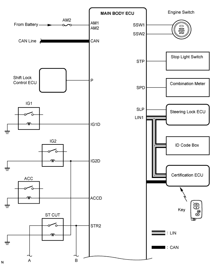
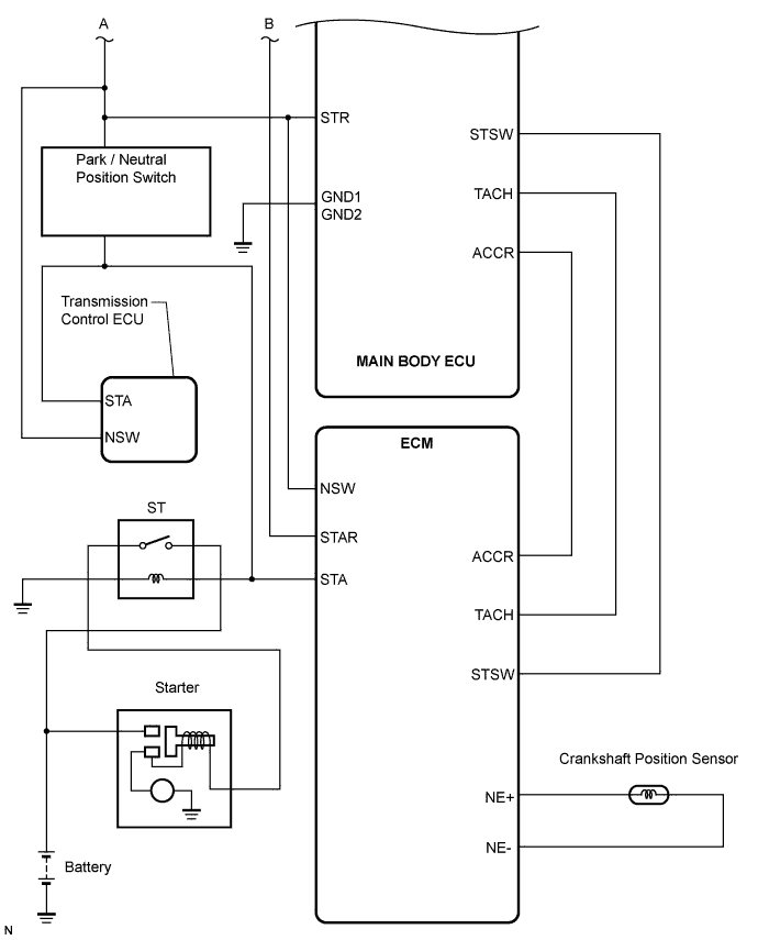
WIRING DIAGRAM
See CRANKING HOLDING FUNCTION CIRCUIT (CAMRY_ACV40 RM000000WZ307KX.html).
INSPECTION PROCEDURE
| EMERGENCY ENGINE START CONTROL |
If there is a malfunction in the stop light switch or STOP fuse, their signals may not be correctly transmitted to the main body ECU. This may result in the engine not starting even if the engine switch is pressed while the brake pedal is depressed and the shift lever is in the P position.
To activate the starter:
Turn the engine switch from off to on (ACC).
Press and hold the engine switch for 15 seconds.
- HINT:
- After the main body ECU, certification ECU, steering lock ECU, ID code box and/or ECM are/is replaced, perform the registration procedures for the engine immobiliser system.
| 1.CHECK ENTRY FUNCTION DETECTION AREA |
Inspect entry detection area.
When the electrical key is in either of the 2 inspection points in the illustration, the shift lever is in the P position and the brake pedal is depressed, check that the engine switch indicator illuminates in green.
- OK:
- Engine switch illuminates in green.
- HINT:
- If the engine switch does not illuminate, perform troubleshooting according to the PROBLEM SYMPTOMS TABLE (CAMRY_ACV40 RM000000XI60BMX.html).
Delete the DTCs (CAMRY_ACV40 RM000000YEH05QX.html).
Check for DTCs again.
- OK:
- DTC is not output.
- HINT:
- If entry and start system (start) DTCs are output (CAMRY_ACV40 RM000000XIZ0ABX.html).
- If entry and start system (entry) DTCs are output (CAMRY_ACV40 RM000000XUD02WX.html).
- If electrical steering lock DTCs are output (CAMRY_ACV40 RM000000XWM02QX.html).
- If engine immobiliser system DTCs are output (CAMRY_ACV40 RM000000QY604VX.html).
- If engine control system DTCs are output (CAMRY_ACV40 RM000002DSC01VX.html).
| 3.CHECK ENGINE SWITCH CONDITION |
Check the power source mode change.
When the key is inside the vehicle and the shift lever is in the P position, check that pressing the engine switch causes the power source mode to change as follows:
- OK:
- off → on (ACC) → on (IG) → off
- HINT:
- If power mode does not change to ON (IG and ACC) (CAMRY_ACV40 RM0000020S906WX.html).
- If power mode does not change to ON (IG) (CAMRY_ACV40 RM0000020SA027X.html).
- If power mode does not change to ON (ACC) (CAMRY_ACV40 RM0000020SB027X.html).
| 4.CHECK CRANKING FUNCTION |
Check the engine cranking function.
When there is fuel in the fuel tank, the key is inside the vehicle, and the shift lever is in the P position, check that depressing the brake pedal and pressing the engine switch crank the engine.
- OK:
- Engine cranks.
| 5.READ VALUE USING INTELLIGENT TESTER (P SIGNAL) |
Connect the intelligent tester to the DLC3.
Turn the engine switch on (IG).
Turn the intelligent tester on.
Enter the following menus: Body / Body / Data List.
Read the Data List according to the displays on the intelligent tester.
Body:Tester Display
| Measurement Item/Range
| Normal Condition
| Diagnostic Note
|
Shift P Sig
| Shift P signal / ON or OFF
| ON: Shift position is P
OFF: Shift position is not P
| -
|
- OK:
- ON (P signal is ON) and OFF (P signal is OFF) appear on the screen.
- HINT:
- If the result is not as specified, perform troubleshooting for DTC B2281 first (CAMRY_ACV40 RM000001LV201ZX.html).
| 6.READ VALUE USING INTELLIGENT TESTER (STOP LIGHT SWITCH) |
Read the Data List according to the display on the intelligent tester.
Body:Tester Display
| Measurement Item/Range
| Normal Condition
| Diagnostic Note
|
Stop Light SW
| Stop light Switch / ON or OFF
| ON: Brake pedal depressed
OFF: Brake pedal released
| -
|
- OK:
- ON (brake pedal depressed) and OFF (brake pedal released) appear on the screen.
- HINT:
- If the result is not as specified, perform troubleshooting for DTC B2284 first (CAMRY_ACV40 RM000000XEW08HX.html).
| 7.READ VALUE USING INTELLIGENT TESTER (STEERING LOCK) |
Read the Data List according to the display on the intelligent tester.
Body:Tester Display
| Measurement Item/Range
| Normal Condition
| Diagnostic Note
|
Str Unlock SW
| Steering lock condition / ON or OFF
| ON: Steering is unlocked (Engine switch on (ACC))
OFF: Steering is locked (Engine switch off)
| -
|
- OK:
- ON (steering is unlocked) and OFF (steering is locked) appear on the screen.
- HINT:
- If the result is not as specified, perform troubleshooting for DTCs B2285 and B2288 first (CAMRY_ACV40 RM000000XIZ0ABX.html).
Check if the steering lock is released when turning the engine switch on (ACC).
- OK:
- The steering lock is released.
| | GO TO STEERING LOCK SYSTEM |
|
|
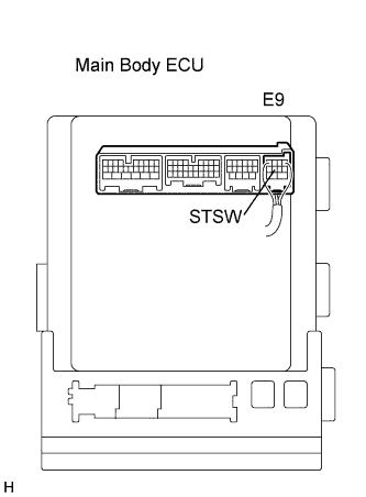
| 9.INSPECT MAIN BODY ECU (STSW VOLTAGE) |
Disconnect the A55 ECM connector.
Measure the voltage according to the value(s) in the table below.
- Standard Voltage:
Tester Connection
| Condition
| Specified Condition
|
E9-4 (STSW) - Body ground
| Brake pedal depressed, engine switch held on (ST)
| Output voltage at terminal AM1 or AM2 is -2 V or more.
|
- HINT:
- If the result is not as specified, perform troubleshooting for DTC B2275 first (CAMRY_ACV40 RM000001LUZ02FX.html).
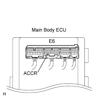
| 10.INSPECT ECM (ACCR VOLTAGE) |
Reconnect the connector.
Measure the voltage according to the value(s) in the table below.
- Standard Voltage:
Tester Connection
| Condition
| Specified Condition
|
E6-3 (ACCR) - IM-9 (GND2)
| Brake pedal depressed, shift lever P position, engine switch is pushed once → on (IG)
| 0.1 to 0.8 V*1 → Output voltage at terminal AM1 or AM2 is -2 V or more.
|
*1: Voltage is output only when the engine is cranking.
- HINT:
- If the result is not as specified, perform troubleshooting for DTC B2276 first (CAMRY_ACV40 RM000001LV8048X.html).
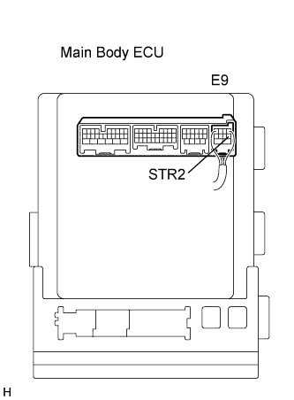
| 11.INSPECT ECM (STR2 VOLTAGE) |
Measure the voltage according to the value(s) in the table below.
- Standard Voltage:
Tester Connection
| Condition
| Specified Condition
|
E9-6 (STR2) - IM-9 (GND2)
| Brake pedal depressed, shift lever P or N position, engine switch on (ST)
| Output voltage at terminal AM1 or AM2 is -3.5 V or more.*1
|
*1: Voltage is output for 0.3 seconds when the engine is cranking to start.
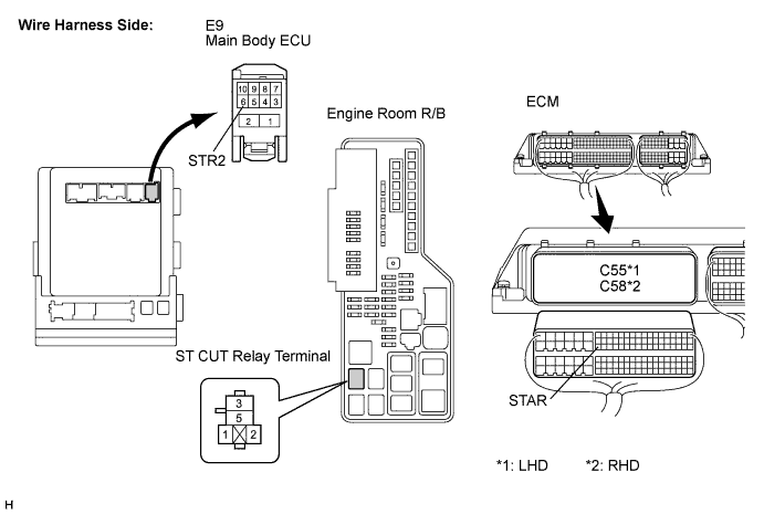
| 12.CHECK WIRE HARNESS (MAIN BODY ECU -ECM - ENGINE ROOM R/B) |
Remove the ST CUT relay from the engine room R/B.
Measure the resistance according to the value(s) in the table below.
- Standard Resistance:
Tester Connection
| Condition
| Specified Condition
|
C55-63 (STAR) - E9-6 (STR2)*1
C58-63 (STAR) - E9-6 (STR2)*2
| Always
| Below 1 Ω
|
C55-63 (STAR) - ST CUT relay terminal - 3*1
C58-63 (STAR) - ST CUT relay terminal - 3*2
| Always
| Below 1 Ω
|
C55-63 (STAR) - Body ground*1
C58-63 (STAR) - Body ground*2
| Always
| 10 kΩ or higher
|
- *1: LHD
- *2: RHD
| | REPAIR OR REPLACE HARNESS OR CONNECTOR |
|
|
| 13.INSPECT RELAY (ST CUT) |
Measure the resistance of the ST CUT relay.
- Standard Resistance:
Tester Connection
| Condition
| Specified Condition
|
3 - 5
| When battery voltage is not applied to terminals 1 and 2
| 10 kΩ or higher
|
3 - 5
| When battery voltage is applied to terminals 1 and 2
| Below 1 Ω
|
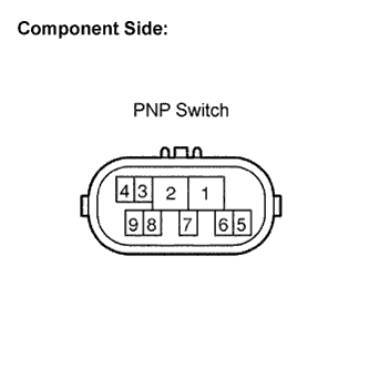
| 14.INSPECT PARK/NEUTRAL POSITION SWITCH |
Disconnect the park/neutral position (PNP) switch connector.
Measure the resistance according the the value(s) in the table below.
- Standard Resistance:
Shift Position
| Tester Connection
| Specified Condition
|
P
| 4 - 9
| Below 1 Ω
|
N
| 4 - 9
| Below 1 Ω
|
Except P and N
| 4 - 9
| 10 kΩ or higher
|
| | REPLACE PARK/NEUTRAL POSITION SWITCH |
|
|
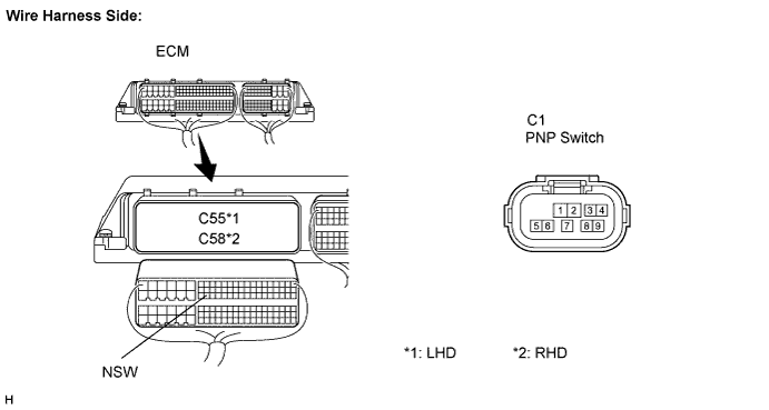
| 15.CHECK HARNESS AND CONNECTOR (PARK/NEUTRAL POSITION SWITCH - ECM) |
Disconnect the C55*1 or C58*2 ECM connector.
Measure the resistance according to the value(s) in the table below.
- Standard Resistance:
Tester Connection
| Condition
| Specified Condition
|
C55-62 (NSW) - C1-4*1
C58-62 (NSW) - C1-4*2
| Always
| Below 1 Ω
|
C55-62 (NSW) - Body ground*1
C58-62 (NSW) - Body ground*2
| Always
| 10 kΩ or higher
|
- *1: for LHD
- *2: for RHD
| | REPAIR OR REPLACE HARNESS OR CONNECTOR |
|
|
Remove the starter relay from the engine room R/B.
Measure the resistance of the starter relay.
- Standard Resistance:
Tester Connection
| Condition
| Specified Condition
|
3 - 5
| When battery voltage is not applied to terminals 1 and 2
| 10 kΩ or higher
|
3 - 5
| when battery voltage is applied to terminals 1 and 2
| Below 1 Ω
|
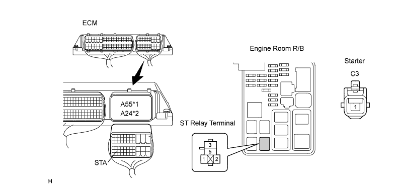
| 17.CHECK HARNESS AND CONNECTOR (ECM AND STARTER - ST RELAY) |
Disconnect the A55*1 or A24*2 ECM connector.
Disconnect the C3 starter connector.
Measure the resistance according the the value(s) in the table below.
- Standard Resistance:
Tester Connection
| Condition
| Specified Condition
|
A55-48 (STA) - ST relay terminal - 1*1
A24-48 (STA) - ST relay terminal - 1*2
| Always
| Below 1 Ω
|
A55-48 (STA) - Body ground*1
A24-48 (STA) - Body ground*2
| Always
| 10 kΩ or higher
|
C3-1 - ST relay terminal - 3
| Always
| Below 1 Ω
|
C3-1 - Body ground
| Always
| 10 kΩ or higher
|
- *1: LHD
- *2: RHD
| | REPAIR OR REPLACE HARNESS OR CONNECTOR |
|
|
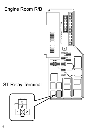
| 18.INSPECT ENGINE ROOM RELAY BLOCK (ST RELAY VOLTAGE) |
Measure the voltage according to the value(s) in the table below.
- Standard Voltage:
Tester Connection
| Condition
| Specified Condition
|
ST relay terminal - 5 - Body ground
| Always
| 9 to 14 V
|
| | REPAIR OR REPLACE HARNESS OR CONNECTOR |
|
|
| 19.INSPECT STARTER ASSEMBLY |
- HINT:
- (CAMRY_ACV40 RM000000YQ201EX.html).
| | REPAIR OR REPLACE STARTER ASSEMBLY |
|
|
| OK |
|
|
|
| REPAIR OR REPLACE HARNESS OR CONNECTOR (PNP SWITCH - ST RELAY, STARTER - BATTERY) |
|
| 20.READ VALUE USING INTELLIGENT TESTER (L CODE) |
Reconnect the connectors.
Connect the intelligent tester to the DLC3.
Turn the engine switch on (IG).
Turn the intelligent tester on.
Enter the following menus: Body / Entry & Start / Data List.
Read the Data List according to the display on the intelligent tester.
- HINT:
- When using the intelligent tester with the engine switch off, turn on and off any of the door courtesy light switches repeatedly at 1.5 second intervals or less until communication between the tester and vehicle starts.
Entry & Start:Tester Display
| Measurement Item/Range
| Normal Condition
| Diagnostic Note
|
L Code Chk
| L code check / ON or NG
| OK: Normal
NG: Malfunction
| Electrical key in the cabin
|
- OK:
- OK is displayed on the screen.
- HINT:
- If the result is not as specified, there may be a malfunction with the steering lock ECU or the ID code box.
| | GO TO ENGINE IMMOBILISER SYSTEM |
|
|
| 21.READ VALUE USING INTELLIGENT TESTER (ENGINE START REQUEST) |
Connect the intelligent tester to the DLC3.
Turn the engine switch on (IG).
Entry & Start:Tester Display
| Measurement Item/Range
| Normal Condition
| Diagnostic Note
|
Start Rqst-Past
| Start request signal response / OK or NG
| OK: Received
NG: Not received
| -
|
- OK:
- OK (received) and NG (not received) appear on the screen.
| | REPLACE CERTIFICATION ECU |
|
|
| 22.READ VALUE USING INTELLIGENT TESTER (S CODE) |
Read the Data List according to the display on the intelligent tester.
Entry & Start:Tester Display
| Measurement Item/Range
| Normal Condition
| Diagnostic Note
|
S Code Chk
| S code check / OK or NG
| OK: Normal
NG: Malfunction
| -
|
- OK:
- OK is displayed on the screen.
- HINT:
- If the result is not as specified, there may be a malfunction with the certification ECU or the ID code box.
| | GO TO ENGINE IMMOBILISER SYSTEM |
|
|
Check the input signal waveform.
Connect an oscilloscope to terminal E68-6 (EFIO) and body ground.
Turn the engine switch on (IG).
Check the signal waveform according to the condition(s) in the table below.
Item
| Condition
|
Tool setting
| 10 V/DIV., 100 ms./DIV.
|
Vehicle condition
| Engine switch on (IG)
|