Dtc B2286 Runnable Signal Malfunction
DESCRIPTION
WIRING DIAGRAM
INSPECTION PROCEDURE
CHECK OPERATION OF TACHOMETER
CHECK DTC OUTPUT (CAN COMMUNICATION SYSTEM)
CHECK HARNESS AND CONNECTOR (MAIN BODY ECU - ECM)
READ VALUE USING INTELLIGENT TESTER
DTC B2286 Runnable Signal Malfunction |
DESCRIPTION
This DTC is output when serial communication signals and CAN communication signals in the circuit between the main body ECU and ECM are inconsistent.- HINT:
- When the main body ECU is replaced with a new one and the negative (-) battery terminal is connected, the power source mode becomes the IG-ON mode. When the battery is removed and reinstalled, the power source mode that was selected when the battery was removed is restored.
- After the main body ECU is replaced, perform the registration procedures for the engine immobiliser system.
DTC No.
| DTC Detection Condition
| Trouble Area
|
B2286
| Serial communication signals and CAN communication signals in the circuit between the main body ECU and ECM are inconsistent.
| - CAN communication system
- ECM
- Main body ECU
- Wire harness or connector
|
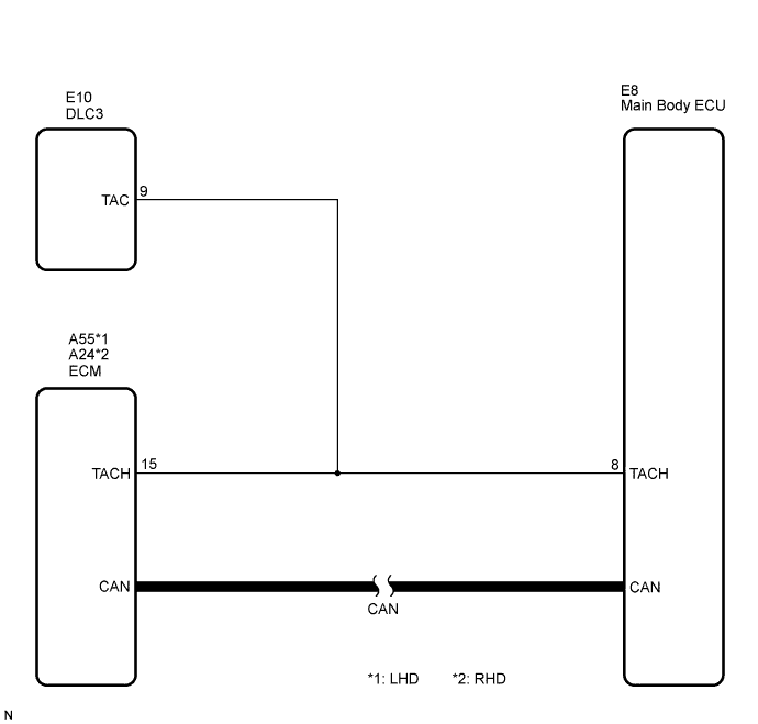
WIRING DIAGRAM
INSPECTION PROCEDURE
| 1.CHECK OPERATION OF TACHOMETER |
Run the engine and check if the function of the tachometer in the combination meter is normal.
- OK:
- Actual engine revolution speed and the revolution indicated on the tachometer are the same.
| | GO TO COMBINATION METER SYSTEM |
|
|
| 2.CHECK DTC OUTPUT (CAN COMMUNICATION SYSTEM) |
Clear the DTCs (CAMRY_ACV40 RM000000YEH05QX.html).
Check for CAN communication system DTC U0146.
- HINT:
- If the DTCs for the CAN communication system malfunction are output, inspect those DTCs first.
- Result:
Result
| Proceed to
|
DTC is not output
| A
|
DTC is output (for LHD)
| B
|
DTC is output (for RHD)
| C
|
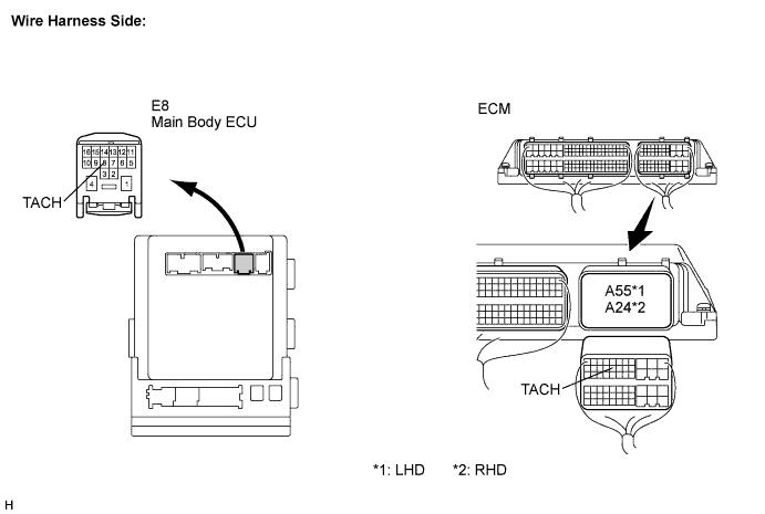
| 3.CHECK HARNESS AND CONNECTOR (MAIN BODY ECU - ECM) |
Disconnect the A55*1 or A24*2 ECM connector.
Disconnect the E8 ECU connector.
Measure the resistance according to the value(s) in the table below.
- Standard Resistance:
Tester Connection
| Condition
| Specified Condition
|
E8-8 (TACH) - A55-15 (TACH)*1
E8-8 (TACH) - A24-15 (TACH)*2
| Always
| Below 1 Ω
|
E8-8 (TACH) or A55-15 (TACH) - Body ground*1
E8-8 (TACH) or A24-15 (TACH) - Body ground*2
| Always
| 10 kΩ or higher
|
- *1: for LHD
- *2: for RHD
| | REPAIR OR REPLACE HARNESS OR CONNECTOR |
|
|
| 4.READ VALUE USING INTELLIGENT TESTER |
Reconnect the connectors.
Connect the intelligent tester to the DLC3.
Turn the engine switch on (IG).
Turn the intelligent tester on.
Enter the following menus: Body / Body / Data List.
Read the Data List according to the display on the intelligent tester.
- HINT:
- When using the intelligent tester with the engine switch off, turn on and off any of the door courtesy light switches repeatedly at 1.5 second intervals or less until communication between the tester and vehicle starts.
Body:Tester Display
| Measurement Item/Range
| Normal Condition
| Diagnostic Note
|
E/G Cond
| Engine condition/STOP or RUN
| STOP: Engine is stopped
RUN: Engine is running
| -
|
- OK:
- STOP (engine is stopped) and RUN (engine is running) appear on the screen.