Oil Pump -- Installation |
| 1. INSTALL TIMING CHAIN CASE OIL SEAL |
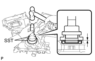
Using SST, tap in a new oil seal until its surface is flush with the timing chain case edge.
- SST
- 09223-22010
09506-35010
- NOTICE:
- Keep the lip free from foreign matter.
- Do not tap on the oil seal at an angle.
- Make sure that the oil seal edge does not stick out of the timing chain case.
 |
| 2. INSTALL TIMING CHAIN COVER SUB-ASSEMBLY |
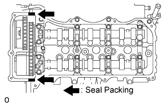
Apply seal packing in a continuous line to the engine unit as shown in the following illustration.
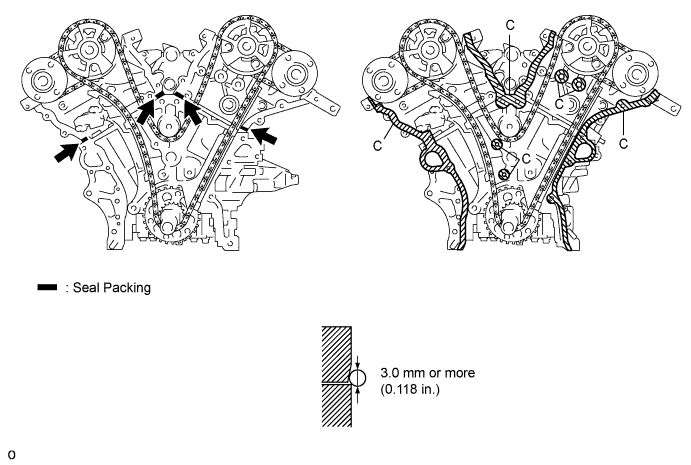
- Seal packing:
- Toyota Genuine Seal Packing Black, Three Bond 1207B or equivalent
- Seal diameter:
- 3.0 mm (0.118 in.)
- NOTICE:
- Be sure to clean and degrease the contact surfaces, especially the surfaces indicated by C in the illustration.
- When the contact surfaces are wet, wipe them with oil-free cloth before applying seal packing.
- Install the chain cover within 3 minutes.
- Do not start the engine for at least 2 hours after installing.
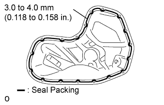
Apply seal packing in a continuous line to the timing chain cover as shown in the following illustration.
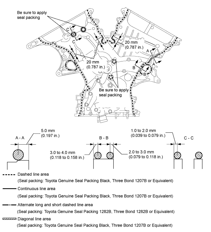
- Seal packing:
- Toyota Genuine Seal Packing Black, Three Bond 1207B or equivalent
- Toyota Genuine Seal Packing Black 1282B, Three Bond 1282B or equivalent
- NOTICE:
- When the contact surfaces are wet, wipe them with oil-free cloth before applying seal packing.
- Install the chain cover within 3 minutes and tighten the bolts within 15 minutes after applying seal packing.
- Do not start the engine for at least 2 hours after installing.
- Apply seal packing as follows:
Area Seal Packing Diameter Application Position from Inside Seal Line Continuous Line Area 4.5 mm or more (0.177 in.) 3.0 to 4.0 mm (0.118 to 0.158 in.) Alternate Long and short Dashed Line Area 3.5 mm or more (0.138 in.) 2.0 to 3.0 mm (0.079 to 0.118 in.) Dashed Line Area 3.5 mm or more (0.138 in.) 3.0 to 4.0 mm (0.118 to 0.158 in.) Diagonal Line Area 6.0 mm or more (0.236 in.) 5.0 mm (0.197 in.)
Install a new gasket.
 |
Align the oil pump's drive rotor spline and the crankshaft as shown in the illustration. Install the spline and chain cover to the crankshaft.
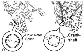 |
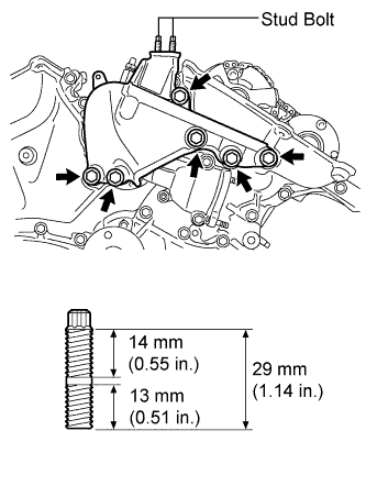
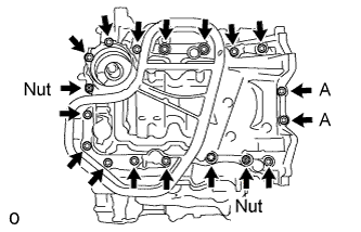
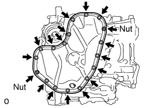
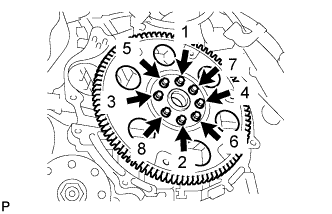
Temporarily tighten the timing chain cover with the 23 bolts and 2 nuts.
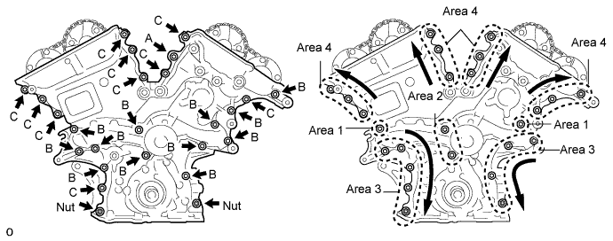
Bolt length Item Length Bolt A 40 mm (1.57 in.) Bolt B 55 mm (2.17 in.) Bolt C 25 mm (0.98 in.) - NOTICE:
- Make sure that there is no oil on the bolt threads.
Fully tighten the bolts in this order: Area 1 and Area 2.
- Torque:
- 21 N*m{214 kgf*cm, 15 ft.*lbf}
Fully tighten the bolts and nuts in this order: Area 3.
- Torque:
- 21 N*m{214 kgf*cm, 15 ft.*lbf}
- HINT:
- Tighten the bolts and nuts in the order of upper to lower as shown in the illustration.
Fully tighten the bolts in this order: Area 4.
- Torque:
- Bolt A:
- 43 N*m{438 kgf*cm, 32 ft.*lbf}
- Except bolt A:
- 21 N*m{214 kgf*cm, 15 ft.*lbf}
- HINT:
- Tighten the bolts in the order of lower to upper as shown in the illustration.
| 3. INSTALL WATER INLET HOUSING |
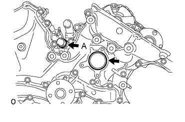
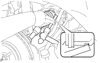
Install 2 new O-rings.
- HINT:
- Apply a small amount of water or soapy water to O-ring (A) in the illustration before installing it.
 |
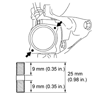
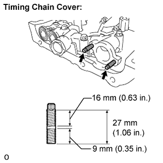
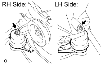
Install the stud bolts.
- Torque:
- 4.0 N*m{41 kgf*cm, 35 in.*lbf}
 |
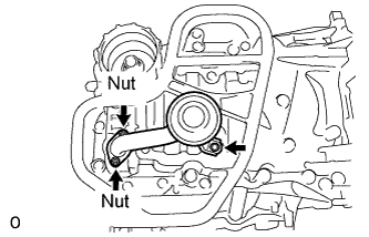
Install the water inlet with the 2 bolts and nut.
- Torque:
- 10 N*m{102 kgf*cm, 7 ft.*lbf}
- NOTICE:
- Be careful that the O-ring does not get caught between the parts.
 |
Connect the water by-pass hose No. 1.
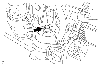
Apply adhesive around the drain cock.
- Adhesive:
- Toyota Genuine Adhesive 1324, Three Bond 1324 or Equivalent
Install the housing drain cock to the water inlet housing.
- Torque:
- 30 N*m{306 kgf*cm, 22 ft.*lbf}
Install the housing plug to the water drain cock.
- Torque:
- 13 N*m{130 kgf*cm, 9 ft.*lbf}
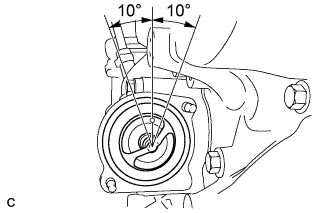
Install a new gasket to the thermostat.
Align the thermostat jiggle valve with the upper stud bolt, and insert the thermostat in the water inlet housing.
- HINT:
- The jiggle valve may be set within 10° of either side of the prescribed positions.
 |
Install the water inlet with the 2 nuts.
- Torque:
- 10 N*m{102 kgf*cm, 7 ft.*lbf}
 |
| 4. INSTALL NO. 1 ENGINE MOUNTING BRACKET FRONT LH |
Install the engine mounting bracket with the 6 bolts.
- Torque:
- 54 N*m{551 kgf*cm, 40 ft.*lbf}
- NOTICE:
- Install the water inlet and mounting bracket within 15 minutes after installing the chain cover.
- Do not start the engine for at least 2 hours after installation.
 |
When replacing a stud bolt, install it by using an E8 "torx" socket wrench.
- Torque:
- 10 N*m{102 kgf*cm, 7 ft.*lbf}
| 5. INSTALL OIL PAN SUB-ASSEMBLY |
When replacing a stud bolt, install it by using an E8 "torx" socket wrench.
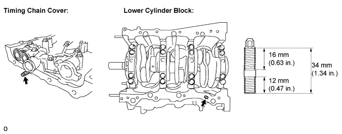
- Torque:
- 10 N*m{102 kgf*cm, 7 ft.*lbf}
Install 2 new O-rings.
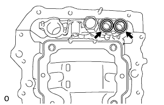 |
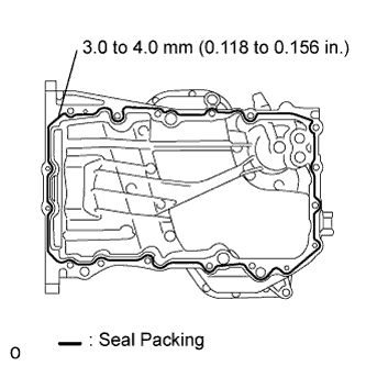
Apply seal packing in a continuous line as shown in the illustration.
- Seal packing:
- Toyota Genuine Seal Packing Black, Three Bond 1207B or equivalent
- Seal diameter:
- 3.0 to 4.0 mm (0.118 to 0.156 in.)
- NOTICE:
- Remove any oil from the contact surface.
- Install the oil pan within 3 minutes after applying seal packing.
- Do not start the engine for at least 2 hours after installing.
 |
Install the oil pan with the 16 bolts and 2 nuts.
- Torque:
- 10 N*m{102 kgf*cm, 7 ft.*lbf} for bolt A
- 21 N*m{214 kgf*cm, 15 ft.*lbf} for bolts except A
 |
| 6. INSTALL OIL STRAINER SUB-ASSEMBLY |
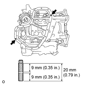
Using an E6 "torx" socket, install the stud bolts as shown in the illustration.
- Torque:
- 4.0 N*m{41 kgf*cm, 35 in.*lbf}
 |
Install a new gasket and the oil strainer with the bolt and 2 nuts.
- Torque:
- 10 N*m{102 kgf*cm, 7 ft.*lbf}
 |
| 7. INSTALL NO. 2 OIL PAN SUB-ASSEMBLY |
Using an E6 "torx" socket, install the stud bolts as shown in the illustration.
- Torque:
- 4.0 N*m{41 kgf*cm, 35 in.*lbf}
 |
Apply seal packing in a continuous line as shown in the illustration.
- Seal packing:
- Toyota Genuine Seal Packing Black, Three Bond 1207B or equivalent
- Seal diameter:
- 3.0 to 4.0 mm (0.118 to 0.156 in.)
- NOTICE:
- Remove any oil from the contact surface.
- Install the oil pan No. 2 within 3 minutes after applying seal packing.
- Do not start the engine for at least 2 hours after installing.
 |
Install the oil pan with the 16 bolts and 2 nuts.
- Torque:
- 10 N*m{102 kgf*cm, 7 ft.*lbf}
 |
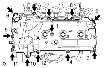
| 8. INSTALL CYLINDER HEAD COVER SUB-ASSEMBLY (for Bank 1) |
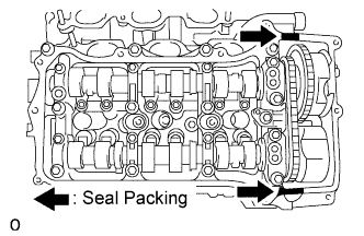
Apply seal packing as shown in the illustration.
- Seal packing:
- Toyota Genuine Seal Packing Black, Three Bond 1207B or equivalent
- NOTICE:
- Remove any oil from the contact surface.
- Install the head cover within 3 minutes after applying seal packing.
- Do not start the engine for at least 2 hours after installing.
 |
Install 3 new gaskets as shown in the illustration.
 |
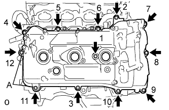
Install a new gasket to the head cover.
Install a head cover with the 12 bolts and a new washer.
- Torque:
- 21 N*m{214 kgf*cm, 15 ft.*lbf} for bolt A
- 10 N*m{102 kgf*cm, 7 ft.*lbf}for bolts except A
- HINT:
- Make sure the tightening torque of bolt 1.
 |
| 9. INSTALL CYLINDER HEAD COVER SUB-ASSEMBLY (for Bank 2) |
Apply seal packing as shown in the illustration.
- Seal packing:
- Toyota Genuine Seal Packing Black, Three Bond 1207B or equivalent
- NOTICE:
- Remove any oil from the contact surface.
- Install the head cover within 3 minutes after applying seal packing.
- Do not start the engine for at least 2 hours after installing.
 |
Install 3 new gaskets as shown in the illustration.
 |
Install a new gasket to the head cover.
Install the head cover with the 12 bolts and a new washer.
- Torque:
- 21 N*m{214 kgf*cm, 15 ft.*lbf} for bolt A
- 10 N*m{102 kgf*cm, 7 ft.*lbf} for bolts except A
- HINT:
- Make sure the tightening torque of bolts 1 and 10.
 |
| 10. INSTALL CRANKSHAFT PULLEY |
Align the pulley set key with the key groove of the pulley, and slide on the pulley.
Using SST, install the pulley bolt.
- SST
- 09213-70011(09213-70020)
09330-00021
- Torque:
- 250 N*m{2,550 kgf*cm, 184 ft.*lbf}
 |
| 11. INSTALL NO. 1 OIL PIPE |
Make sure that there is no foreign matter on the mesh of the oil control valve filter LH.
- NOTICE:
- Do not touch the mesh when installing the oil control valve filter.
Install the oil control valve filter LH to the oil pipe union. Install new gaskets and temporarily install the oil pipe (on the head cover side).
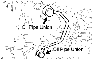 |
Install a new gasket and temporarily install the oil pipe (on the cylinder head side) with the oil check valve bolt.
Tighten the oil pipe union (on the head cover side).
- Torque:
- 65 N*m{663 kgf*cm, 48 ft.*lbf}
Tighten the oil pipe union (on the cylinder head side).
- Torque:
- 65 N*m{663 kgf*cm, 48 ft.*lbf}
- NOTICE:
- If the link that connects the gaskets is broken, remove the connecting link by using nippers or similar tools.
| 12. INSTALL OIL PIPE |
Make sure that there is no foreign matter on the mesh of the oil control valve filter RH.
- NOTICE:
- Do not touch the mesh when installing the oil control valve filter.
Install the oil control valve filter RH to the oil pipe union. Install new gaskets and temporarily install the oil pipe (on the head cover side).
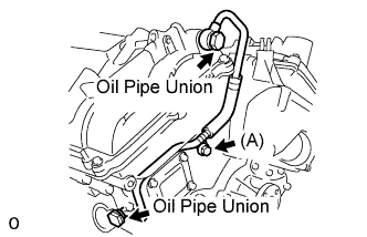 |
Install a new gasket and temporarily install the oil pipe (on the cylinder head side) with the oil check valve bolt.
Install the bolt (A) to the cylinder head.
- Torque:
- 10 N*m{102 kgf*cm, 7 ft.*lbf}
Tighten the oil pipe union (on the head cover side).
- Torque:
- 65 N*m{663 kgf*cm, 48 ft.*lbf}
Tighten the oil pipe union (on the cylinder head side).
- Torque:
- 65 N*m{663 kgf*cm, 48 ft.*lbf}
- NOTICE:
- If the link that connects the gaskets is broken, remove the connecting link by using nippers or similar tools.
| 13. INSTALL NO. 1 VACUUM SWITCHING VALVE |
Install the bolt and No. 1 vacuum switching valve.
- Torque:
- 10 N*m{102 kgf*cm, 7 ft.*lbf}
 |
| 14. INSTALL RADIO SETTING CONDENSER |
Install the 2 bolts and 2 radio setting condensers.
- Torque:
- 10 N*m{102 kgf*cm, 7 ft.*lbf}
 |
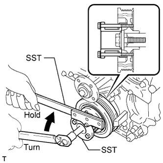
| 15. INSTALL WATER PUMP PULLEY |
Temporarily install the water pump pulley with the 4 bolts.
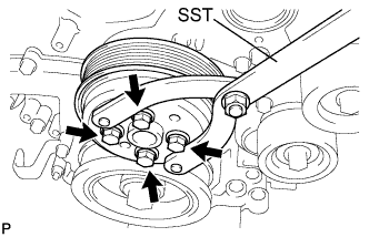 |
Using SST, hold the water pump pulley.
- SST
- 09960-10010(09962-01000,09963-00700)
Tighten the 4 bolts.
- Torque:
- 21 N*m{214 kgf*cm, 15 ft.*lbf}
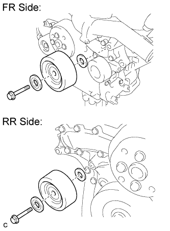
| 16. INSTALL NO. 2 IDLER PULLEY SUB-ASSEMBLY |
Install the No. 2 idler pulley sub-assembly and 2 plates with the bolt.
- Torque:
- 54 N*m{550 kgf*cm, 40 ft.*lbf}
- HINT:
- Plate diameter:
- Idler pulley cover plate: 33.6 mm (1.32 in.)
- No. 2 idler pulley cover plate: 37.8 mm (1.49 in.)
 |
| 17. INSTALL NO. 2 TIMING GEAR COVER |
Install the No. 2 timing gear cover with the 2 bolts.
- Torque:
- 6.0 N*m{61 kgf*cm, 53 in.*lbf}
 |
| 18. INSTALL V-RIBBED BELT TENSIONER ASSEMBLY |
Temporarily install the V-ribbed belt tensioner with the 5 bolts.
- HINT:
- Each bolt length is as follows:
- A: 70 mm (2.76 in.)
- B: 33 mm (1.30 in.)
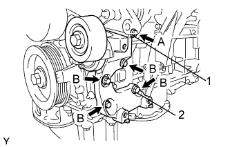 |
Install the V-ribbed belt tensioner by tightening the bolt 1 and bolt 2 in the order shown in the illustration.
- Torque:
- 43 N*m{438 kgf*cm, 32 ft.*lbf}
Tighten the other bolts.
- Torque:
- 43 N*m{438 kgf*cm, 32 ft.*lbf}
| 19. INSTALL ENGINE MOUNTING BRACKET RH |
Install the engine mounting bracket RH with the 3 bolts.
- Torque:
- 54 N*m{551 kgf*cm, 40 ft.*lbf}
 |
| 20. INSTALL EXHAUST MANIFOLD SUB-ASSEMBLY LH |
Install a new gasket as shown in the illustration.
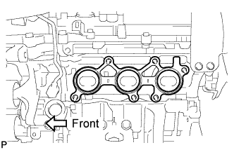 |
Install the exhaust manifold sub-assembly LH with the 6 nuts.
- Torque:
- 21 N*m{214 kgf*cm, 15 ft.*lbf}
 |
| 21. INSTALL NO. 2 EXHAUST MANIFOLD HEAT INSULATOR |
Install the No. 2 insulator with the 3 bolts.
- Torque:
- 8.5 N*m{87 kgf*cm, 75 in.*lbf}
 |
| 22. INSTALL NO. 2 MANIFOLD STAY |
Install the No. 2 manifold stay with the bolt and nut.
- Torque:
- 34 N*m{347 kgf*cm, 25 ft.*lbf}
 |
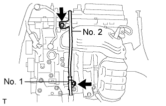
| 23. INSTALL OIL LEVEL GAUGE GUIDE SUB-ASSEMBLY |
Install 2 new O-rings to the oil level gauge guide.
 |
Apply a light coat of engine oil to the O-rings.
Push in the oil level gauge guide end into the guide hole.
Install the oil level gauge guide No. 1 with the bolt.
- Torque:
- 21 N*m{214 kgf*cm, 15 ft.*lbf}
Install the oil level gauge guide No. 2 with the bolt.
- Torque:
- 21 N*m{214 kgf*cm, 15 ft.*lbf}
Install the oil level gauge.
| 24. INSTALL EXHAUST MANIFOLD SUB-ASSEMBLY RH |
Install a new gasket as shown in the illustration.
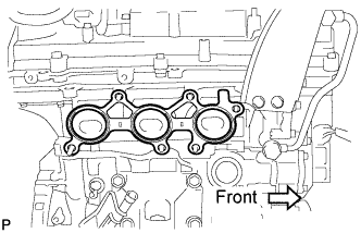 |
Install the exhaust manifold sub-assembly RH with the 6 nuts.
- Torque:
- 21 N*m{214 kgf*cm, 15 ft.*lbf}
 |
| 25. INSTALL NO. 2 ENGINE MOUNTING STAY RH |
Install the No. 2 mounting stay RH with the bolt.
- Torque:
- 21 N*m{214 kgf*cm, 15 ft.*lbf}
| 26. INSTALL IGNITION COIL ASSEMBLY |
Install the 6 ignition coil assemblies with the 6 bolts.
- Torque:
- 10 N*m{102 kgf*cm, 7 ft.*lbf}
| 27. INSTALL INTAKE AIR SURGE TANK ASSEMBLY |
- NOTICE:
- Do not apply oil to the bolts used to install the components listed below:
| Components | ||
| Surge Tank and Intake Manifold | ||
| No. 1 Surge Tank Stay and Cylinder Head Cover | ||
| No. 1 Surge Tank Stay and Surge Tank | ||
| Throttle Body Bracket and Cylinder Head Cover | ||
| Throttle Body Bracket and Surge Tank |
Install a new gasket to the intake air surge tank.
Using a 5 mm hexagon socket wrench, install the 4 bolts and 2 nuts.
- Torque:
- Bolt:
- 18 N*m{184 kgf*cm, 13 ft.*lbf}
- Nut:
- 16 N*m{163 kgf*cm, 12 ft.*lbf}
 |
Install the throttle body bracket, No. 1 surge tank stay and 4 bolts.
- Torque:
- 21 N*m{214 kgf*cm, 15 ft.*lbf}
Connect the connector.
 |
Install the vacuum hose clamp with the bolt.
- Torque:
- 5.4 N*m{55 kgf*cm, 48 in.*lbf}
 |
Connect the No. 1 ventilation hose.
Install the clamp and connect the throttle body assembly connector (*3).
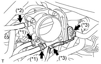 |
Connect the vapor feed hose (*2).
Connect the 2 water by-pass hoses to the throttle body assembly (*1).
| 28. REMOVE ENGINE STAND |
| 29. INSTALL DRIVE PLATE AND RING GEAR SUB-ASSEMBLY |
Using SST, hold the crankshaft.
- SST
- 09213-70011(09213-70020)
09330-00021
 |
Apply adhesive to 2 or 3 threads of the mounting bolt end.
- Adhesive:
- Toyota Genuine Adhesive 1324, Three Bond 1324 or equivalent.
Install the front spacer, drive plate and rear spacer on the crankshaft.
Install and tighten the 8 mounting bolts uniformly in several steps.
- Torque:
- 83 N*m{850 kgf*cm, 61 ft.*lbf}
 |
| 30. INSTALL AUTOMATIC TRANSAXLE ASSEMBLY |
| 31. INSTALL STARTER ASSEMBLY |
Install the starter assembly with the 2 bolts.
- Torque:
- 37 N*m{380 kgf*cm, 28 ft.*lbf}
 |
Connect the wire harness to terminal 30 and install the nut. Then, attach the terminal cap.
- Torque:
- 9.8 N*m{100 kgf*cm, 87 in.*lbf}
Connect the terminal 50 connector to the starter assembly.
| 32. INSTALL ENGINE WIRE |
| 33. INSTALL FRONT DRIVE SHAFT ASSEMBLY LH |
Coat the spline of the inboard joint shaft assembly with ATF.
 |
Align the shaft splines and install the drive shaft assembly LH with a brass bar and hammer.
- NOTICE:
- Set the shaft snap ring with the opening side facing down.
- Be careful not to damage the drive shaft dust cover, boot, and oil seal.
- Move the drive shaft assembly while keeping it level.
| 34. INSTALL FRONT DRIVE SHAFT ASSEMBLY RH |
Coat the spline of the inboard joint shaft assembly with ATF.
 |
Install the front drive shaft the assembly RH.
Using a screwdriver, install a new bearing bracket hole snap ring.
- NOTICE:
- Do not damage the boot and oil seal.
- Move the drive shaft assembly while keeping it level.
Install a new bolt.
- Torque:
- 32 N*m{330 kgf*cm, 24 ft.*lbf}
| 35. INSTALL FRONT FRAME ASSEMBLY |
Install the engine mounting insulators RH and LH with the 2 nuts.
- Torque:
- 95 N*m{969 kgf*cm, 70 ft.*lbf}
 |
Install the engine mounting insulator FR with the bolt.
- Torque:
- 87 N*m{887 kgf*cm, 64 ft.*lbf}
 |
Connect the connector and clamp.
 |
Connect the 2 clamps.
 |
| 36. INSTALL VANE PUMP ASSEMBLY |
Install the vane pump with the 2 bolts.
- Torque:
- 43 N*m{438 kgf*cm, 32 ft.*lbf}
 |
Install the pressure feed tube clamp bolt.
- Torque:
- 9.8 N*m{100 kgf*cm, 87 in.*lbf}
Connect the power steering oil pressure switch connector.
| 37. INSTALL ENGINE ASSEMBLY WITH TRANSAXLE |