Water Pump -- Installation |
| 1. INSTALL WATER PUMP ASSEMBLY |
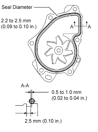
Remove any old seal packing material from the contact surface.
Apply a continuous line of seal packing as shown in the illustration.
- Seal packing:
- Toyota Genuine Seal Packing Black, Three Bond 1207B or Equivalent
- Standard seal diameter:
- 2.2 to 2.5 mm (0.09 to 0.10 in.)
- NOTICE:
- Remove any oil from the contact surface.
- The parts must be set within 3 minutes after applying seal packing. Otherwise, the material must be removed and reapplied.
 |
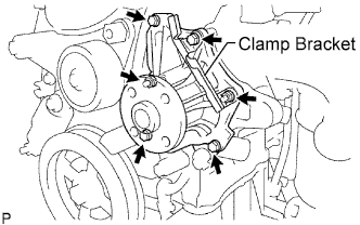
Install the water pump and clamp bracket with the 4 bolts and 2 nuts.
- Torque:
- 9.0 N*m{92 kgf*cm, 80 in.*lbf}
 |
Install the wire of the crankshaft position sensor onto the clamp bracket.
 |
Install the clamp of the crankshaft position sensor onto the water pump.
| 2. INSTALL WATER PUMP PULLEY |
 |
Using SST, install the water pump pulley with the 4 bolts.
- SST
- 09960-10010(09962-01000,09963-00700)
- Torque:
- 26 N*m{265 kgf*cm, 19 ft.*lbf}
| 3. INSTALL GENERATOR ASSEMBLY |
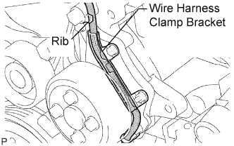
Confirm that the wire harness of the crankshaft position sensor is secured to the wire harness clamp bracket through the back of the rib of the timing chain cover.
 |
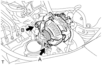
Install the generator assembly with the 2 bolts.
- Torque:
- Bolt A:
- 21 N*m{215 kgf*cm, 16 ft.*lbf}
- Bolt B:
- 52 N*m{530 kgf*cm, 38 ft.*lbf}
 |
Install the generator wire to terminal B with the nut.
- Torque:
- 9.8 N*m{100 kgf*cm, 87 in.*lbf}
 |
Install the clamp bracket with the bolt.
- Torque:
- 8.4 N*m{86 kgf*cm, 74 in.*lbf}
Attach the clamp and connect the generator connector to the generator.
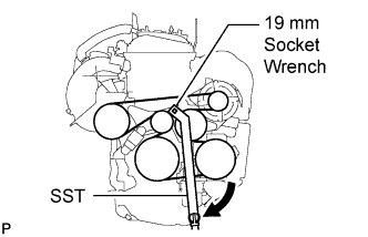
| 4. INSTALL V-RIBBED BELT |
Using SST and 19 mm socket wrench, loosen the V-ribbed belt tensioner arm clockwise, then install the V-ribbed belt.
- SST
- 09216-42010
- NOTICE:
- Be sure to connect SST and the tools so that they are in line during use.
- When retracting the tensioner, turn it clockwise slowly for 3 seconds or more. Do not apply force rapidly.
- After the tensioner is fully retracted, do not apply force any more than necessary.
 |
After installing the V-ribbed belt, check that it fits properly in the ribbed grooves. Check to confirm that the belt has not slipped out of the grooves on the bottom of the crank pulley by hand.
| 5. INSTALL NO. 2 ENGINE MOUNTING BRACKET RH |
Install the 3 bolts and No. 2 mounting bracket RH.
- Torque:
- 52 N*m{531 kgf*cm, 38 ft.*lbf}
 |
| 6. INSTALL ENGINE MOVING CONTROL ROD SUB-ASSEMBLY |
Install the engine moving control rod with the 3 bolts.
- Torque:
- 64 N*m{653 kgf*cm, 47 ft.*lbf}
 |
Install the ground cable with the bolt.
- Torque:
- 8.4 N*m{85 kgf*cm, 74 in.*lbf}
 |
| 7. INSTALL NO. 2 ENGINE MOUNTING STAY RH |
Install the No. 2 mounting stay RH with the 2 bolts.
- Torque:
- 64 N*m{653 kgf*cm, 47 ft.*lbf}
 |
| 8. CONNECT CABLE TO NEGATIVE BATTERY TERMINAL |
- Torque:
- 6.9 N*m{70 kgf*cm, 61 in.*lbf}
| 9. ADD ENGINE COOLANT |
Close the radiator drain cock plug and 2 cylinder block drain cock plugs.
- Torque:
- 13 N*m{130 kgf*cm, 9 ft.*lbf} for cylinder block drain cock plug
Slowly fill the radiator with TOYOTA Super Long Life Coolant (SLLC).
- Specified capacity:
- 6.2 liters (6.6 US qts, 5.5 lmp. qts)
- HINT:
- TOYOTA vehicles are filled with TOYOTA SLLC at the factory. In order to avoid damage to the engine cooling system and other technical problems, only use TOYOTA SLLC or similar high quality ethylene glycol based non-silicate, non-amine, non-nitrite, non-borate coolant with long-life hybrid organic acid technology (coolant with long-life hybrid organic acid technology consists of a combination of low phosphates and organic acids).
- Contact your TOYOTA dealer for further details.
Slowly pour coolant into the radiator reservoir tank until it reaches the FULL line.
Press the inlet and outlet radiator hoses several times by hand, and then check the level of the coolant.
If the coolant level is low, add coolant.
Install the radiator cap sub-assembly and reservoir tank cap.
Start the engine, and warm it up.
- HINT:
- Adjust the air conditioner set temperature to MAX (HOT).
Stop the engine, and wait until the engine coolant cools down.
Add engine coolant to the FULL line on the radiator reservoir.
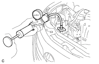
| 10. CHECK FOR ENGINE COOLANT LEAKS |
 |
- NOTICE:
- Before performing each inspection, turn the A/C switch OFF.
- CAUTION:
- Do not remove the radiator cap while the engine and radiator are still hot. Pressurized, hot engine coolant and steam may be released and cause serious burns.
Fill the radiator with coolant and attach a radiator cap tester.
Warm up the engine.
Using a radiator cap tester, increase the pressure inside the radiator to 118 kPa (1.2 kgf*cm, 17 psi), and check that the pressure does not drop.
If the pressure drops, check the hoses, radiator and water pump for leaks. If no external leaks are found, check the heater core, cylinder block and cylinder head.
| 11. INSTALL ENGINE UNDER COVER LH |
| 12. INSTALL ENGINE UNDER COVER RH |