DISCONNECT TRANSMISSION CONTROL CABLE ASSEMBLY (for Automatic Transaxle)
DISCONNECT TRANSMISSION CONTROL CABLE ASSEMBLY (for Manual Transaxle)
REMOVE CLUTCH RELEASE CYLINDER ASSEMBLY (for Manual Transaxle)
REMOVE DRIVE PLATE & TORQUE CONVERTER CLUTCH SETTING BOLT (for Automatic Transaxle)
SEPARATE AUTOMATIC TRANSAXLE ASSEMBLY (for Automatic Transaxle)
REMOVE DRIVE PLATE & RING GEAR SUB-ASSEMBLY (for Automatic Transaxle)
Engine Assembly -- Removal |
| 1. DISCHARGE FUEL SYSTEM PRESSURE |
- HINT:
| 2. DISCONNECT CABLE FROM NEGATIVE BATTERY TERMINAL |
| 3. PLACE FRONT WHEELS FACING STRAIGHT AHEAD |
| 4. REMOVE FRONT WHEELS |
| 5. REMOVE ENGINE UNDER COVER LH |
| 6. REMOVE ENGINE UNDER COVER RH |
| 7. REMOVE FRONT FENDER APRON SEAL RH |
| 8. DRAIN ENGINE OIL |
Remove the oil filler cap.
Remove the oil drain plug and drain the oil into a container.
| 9. DRAIN ENGINE COOLANT |
- NOTICE:
- Do not remove the radiator cap sub-assembly while the engine and radiator are still hot. Pressurized, hot engine coolant and steam may be released and cause serious burns.
Remove the radiator cap sub-assembly from the radiator assembly.
Loosen the radiator drain cock plug and cylinder block drain cock plug, then drain the coolant.
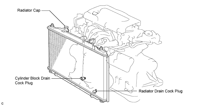
- HINT:
- Collect the coolant in a container and dispose of it according to the regulations in your area.
| 10. DRAIN AUTOMATIC TRANSAXLE FLUID (for Automatic Transaxle) |
Using a 6 mm socket hexagon wrench, remove the drain plug and gasket, and drain ATF.
Install a new gasket and the drain plug.
- Torque:
- 49 N*m{500 kgf*cm, 36 ft.*lbf}
| 11. DRAIN MANUAL TRANSAXLE OIL (for Manual Transaxle) |
Remove the filler plug and the gasket.
Remove the drain plug and gasket, and drain the manual transaxle oil.
Install a new gasket and the drain plug.
- Torque:
- 49 N*m{500 kgf*cm, 36 ft.*lbf}
| 12. DRAIN BRAKE FLUID (for Manual Transaxle) |
- NOTICE:
- Stop the engine and depress the brake pedal several times until no vacuum is left in the brake booster.
- If the brake fluid leaks onto any painted surface, wash off and remove the brake fluid completely.
| 13. REMOVE WINDSHIELD WIPER LINK ASSEMBLY |
- HINT:
| 14. REMOVE COWL TOP PANEL OUTER SUB-ASSEMBLY |
Remove the 4 bolts, 4 nuts and outer cowl top panel sub-assembly.
 |
| 15. REMOVE NO. 1 ENGINE COVER SUB-ASSEMBLY |
Remove the 2 nuts and cover.
 |
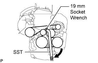
| 16. REMOVE V-RIBBED BELT |
Using SST and 19 mm socket wrench, loosen the V-ribbed belt tensioner arm clockwise, then remove the V-ribbed belt.
- SST
- 09216-42010
- NOTICE:
- Be sure to connect SST and the tools so that they are in line during use.
- When retracting the tensioner, turn it clockwise slowly for 3 seconds or more. Do not apply force rapidly.
- After the tensioner is fully retracted, do not apply force any more than necessary.
 |
| 17. REMOVE AIR CLEANER INLET ASSEMBLY |
Remove the 2 bolts, clamp and air cleaner inlet.
 |
| 18. REMOVE AIR CLEANER CAP SUB-ASSEMBLY |
Disconnect the mass air flow meter connector (*1).
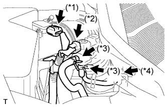 |
Disconnect the purge VSV connector (*2).
Disconnect the 2 purge VSV vacuum hoses (*3).
Disconnect the purge line hose from the clamp (*4).
Disconnect the No. 2 ventilation hose from the air cleaner hose.
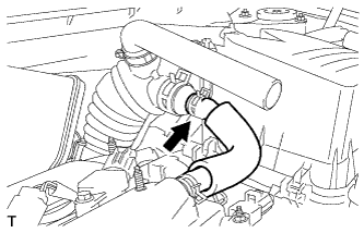 |
Lock the No. 1 air cleaner hose clamp, and then disconnect the No. 1 air cleaner hose from the throttle body.
 |
Remove the 2 bolts and air cleaner cap.
 |
Remove the air cleaner filter element from the air cleaner case.
| 19. REMOVE AIR CLEANER CASE SUB-ASSEMBLY |
Disconnect the hose clamp.
 |
Remove the 3 bolts and air cleaner case.
| 20. REMOVE BATTERY |
Loosen the bolt and nut, and remove the battery clamp.
 |
Remove the battery and battery tray.
| 21. REMOVE NO. 2 ENGINE MOUNTING STAY RH |
Remove the 2 bolts and No. 2 mounting stay RH.
 |
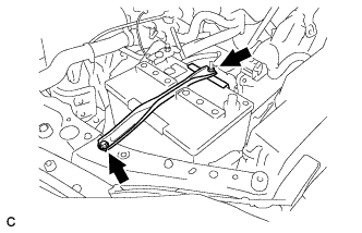
| 22. REMOVE ENGINE MOVING CONTROL ROD SUB-ASSEMBLY |
Remove the bolt and disconnect the ground cable.
 |
Remove the 3 bolts and the engine moving control rod with bracket.
 |
| 23. REMOVE NO. 2 ENGINE MOUNTING BRACKET RH |
Remove the 3 bolts and No. 2 mounting bracket RH.
 |
| 24. DISCONNECT NO. 1 VACUUM HOSE CONNECTOR |
Remove the clamp and disconnect the vacuum hose connector.
 |
| 25. DISCONNECT RADIATOR HOSE INLET |
Remove the clamp and disconnect the radiator hose inlet.
 |
| 26. DISCONNECT RADIATOR HOSE OUTLET |
Remove the clamp and disconnect the radiator hose outlet.
 |
| 27. DISCONNECT OIL COOLER INLET HOSE (for Automatic Transaxle) |
Disconnect the oil cooler inlet hose from the radiator assembly.
 |
| 28. DISCONNECT OIL COOLER OUTLET HOSE (for Automatic Transaxle) |
Disconnect the oil cooler outlet hose from the radiator assembly.
 |
| 29. DISCONNECT HEATER WATER HOSE INLET |
Disconnect the heater inlet water hose.
 |
| 30. DISCONNECT HEATER WATER HOSE OUTLET |
Disconnect the heater outlet water hose.
 |
| 31. REMOVE ECM |
- HINT:
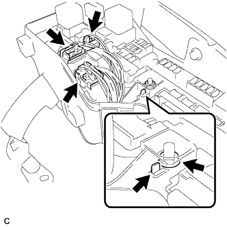
| 32. DISCONNECT ENGINE WIRE |
Disconnect the engine wire from the engine room relay block.
Remove the nut and separate the wire harness.
Using a screwdriver, unlock the engine room R/B. Pull the engine room R/B upward.
Disconnect the engine wire connectors.
 |
Remove the clamp from the bracket.
 |
Remove the 2 bolts and clamp from the body.
 |
| 33. DISCONNECT TRANSMISSION CONTROL CABLE ASSEMBLY (for Automatic Transaxle) |
Remove the clip and nut, and separate the control lever.
 |
Separate the clamp and separate the cable from the transaxle.
| 34. DISCONNECT TRANSMISSION CONTROL CABLE ASSEMBLY (for Manual Transaxle) |
Remove the 2 clips and 2 washers and disconnect the 2 cables from the transaxle.
 |
Remove the 2 clips and disconnect the 2 cables from the control cable bracket.
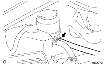
| 35. DISCONNECT NO. 1 OIL RESERVOIR TO PUMP HOSE |
Disconnect the No. 1 oil reservoir to pump hose.
 |
| 36. DISCONNECT RETURN TUBE SUB-ASSEMBLY |
Disconnect the return tube sub-assembly.
 |
| 37. REMOVE CLUTCH ACCUMULATOR ASSEMBLY (for Manual Transaxle) |
- HINT:
| 38. REMOVE CLUTCH RELEASE CYLINDER ASSEMBLY (for Manual Transaxle) |
- HINT:
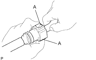
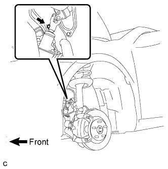
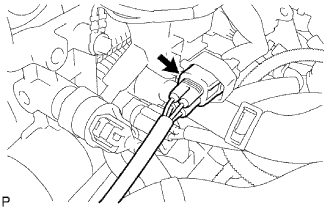
| 39. DISCONNECT FUEL TUBE SUB-ASSEMBLY |
Remove the No. 1 fuel pipe clamp.
 |
Disconnect the connector from the tube while pinching part A with your fingers as shown in the illustration.
- NOTICE:
- Check for contamination in the pipe and around the connector. Clean if necessary and then disconnect the connector.
- Disconnect the connector by hand.
- Do not bend, fold or rotate the nylon tube.
- If the pipe and connector are stuck together, push and pull the connector until it becomes free.
- Put the pipe and connector ends in vinyl bags to prevent damage and contamination.
 |
| 40. REMOVE GENERATOR ASSEMBLY |
Disconnect the generator connector.
 |
Remove the nut and disconnect the wire harness from terminal B.
Remove the bolt and wire harness clamp bracket.
Remove the wire harness clamps.
Remove the 2 bolts and generator assembly.
 |
| 41. SEPARATE COMPRESSOR AND MAGNETIC CLUTCH |
Disconnect the connector.
 |
Remove the 4 bolts and separate the compressor.
- HINT:
- Hang up the hoses instead of detaching them.
| 42. REMOVE FRONT EXHAUST PIPE ASSEMBLY |
- HINT:
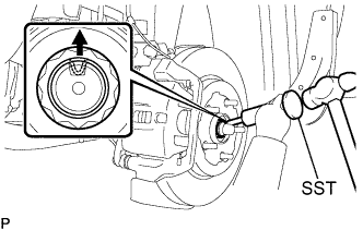
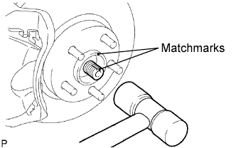
| 43. REMOVE FRONT AXLE HUB NUT LH |
Using SST and a hammer, release the staked part of the front axle hub nut.
- SST
- 09930-00010
- NOTICE:
- Loosen the staked part of the nut completely, otherwise the thread of the drive shaft may be damaged.
 |
While applying the brakes, remove the front axle hub nut.
| 44. REMOVE FRONT AXLE HUB NUT RH |
- HINT:
- Use the same procedures described for the LH side.
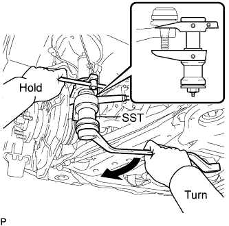
| 45. REMOVE FRONT STABILIZER LINK ASSEMBLY LH |
Remove the nut and separate the front stabilizer link assembly.
- HINT:
- If the ball joint turns together with the nut, use a hexagon wrench (6 mm) to hold the stud.
 |
| 46. REMOVE FRONT STABILIZER LINK ASSEMBLY RH |
- HINT:
- Use the same procedures described for the LH side.
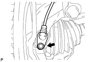
| 47. REMOVE FRONT SPEED SENSOR LH |
Remove the bolt and clip, and separate the speed sensor wire and flexible hose from the shock absorber.
 |
Remove the bolt and separate the speed sensor from the steering knuckle.
- NOTICE:
- Prevent foreign matter from adhering to the speed sensor.
- Be careful not to damage the speed sensor.
 |
| 48. REMOVE FRONT SPEED SENSOR RH |
- HINT:
- Use the same procedures described for the LH side.
| 49. DISCONNECT TIE ROD ASSEMBLY LH |
Remove the cotter pin and nut.
 |
Using SST, separate the tie rod end sub-assembly from the steering knuckle.
- SST
- 09628-00011
- NOTICE:
- Make sure that the string of the SST is securely tied to the vehicle.
- Be careful not to damage the ball joint dust cover.
- Be careful not to damage the steering knuckle.
- Be careful not to damage the front disc brake dust cover.
| 50. DISCONNECT TIE ROD ASSEMBLY RH |
- HINT:
- Use the same procedures described for the LH side.
| 51. DISCONNECT FRONT SUSPENSION LOWER NO. 1 ARM LH |
Remove the bolt and 2 nuts, and separate the front suspension lower No. 1 arm from the lower ball joint.
 |
| 52. DISCONNECT FRONT SUSPENSION LOWER NO. 1 ARM RH |
- HINT:
- Use the same procedures described for the LH side.
| 53. SEPARATE FRONT AXLE ASSEMBLY LH |
Put matchmarks on the front drive shaft assembly and the axle hub.
 |
Using a plastic hammer, separate the front drive shaft assembly from the front axle assembly.
- NOTICE:
- Be careful not to damage the drive shaft boot and speed sensor rotor.
| 54. SEPARATE FRONT AXLE ASSEMBLY RH |
- HINT:
- Use the same procedures described for the LH side.
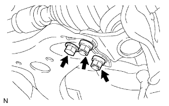
| 55. REMOVE DRIVE PLATE & TORQUE CONVERTER CLUTCH SETTING BOLT (for Automatic Transaxle) |
Remove the flywheel housing under cover.
 |
Turn the crankshaft to gain access and remove the 6 bolts while holding the crankshaft pulley bolt with a wrench.
- HINT:
- There will be one black colored bolt.
 |
| 56. REMOVE NO. 1 EXHAUST PIPE SUPPORT BRACKET |
Remove the 2 bolts and exhaust pipe support bracket.
| 57. SEPARATE STEERING SLIDING YOKE |
Secure the steering wheel with the seat belt in order to prevent rotation.
- HINT:
- This operation is useful to prevent damage to the spiral cable.
 |
Remove the bolt and slide the steering sliding yoke.
- NOTICE:
- Do not separate the steering sliding yoke from the power steering link assembly.
 |
Put matchmarks on the steering sliding yoke and the power steering link assembly.
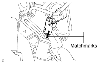 |
Separate the steering sliding yoke from the power steering link assembly.
| 58. REMOVE ENGINE ASSEMBLY WITH TRANSAXLE |
Set the engine lifter.
 |
Remove the 4 bolts, 2 nuts and frame side rail plate RH and LH.
Remove the 4 bolts, 2 nuts and front suspension member brace rear RH and LH.
 |
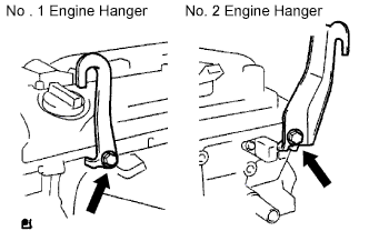
Carefully remove the engine assembly from the vehicle.
Install the 2 engine hangers as shown in the illustration.
Parts No.:Parts Parts No. No. 1 Engine hanger 12281-28010 No. 2 Engine hanger 12282-28010 Bolt 91512-61020 - Torque:
- 38 N*m{387 kgf*cm, 28 ft.*lbf}
 |
Using a chain block and an engine sling device, hang the engine assembly.
| 59. REMOVE VANE PUMP ASSEMBLY |
Disconnect the oil pressure switch connector.
 |
Loosen the 2 bolts and remove the vane pump from the engine.
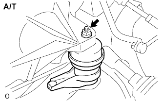
| 60. REMOVE FRONT FRAME ASSEMBLY |
A/T:
Remove the nut from the engine mounting insulator LH.
 |
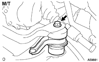
M/T:
Remove the bolt from the engine mounting insulator LH.
 |
Remove the nut from the engine mounting insulator RH.
 |
Remove the bolt from the engine mounting insulator FR.
 |
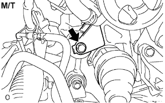
M/T:
Remove the bolt from the engine lateral control rod.
 |
Raise the engine assembly and separate the front frame.
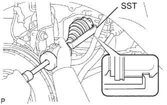
| 61. REMOVE FRONT DRIVE SHAFT ASSEMBLY LH |
Using SST, remove the front drive shaft assembly LH.
- SST
- 09520-01010
09520-24010(09520-32040)
- NOTICE:
- Be careful not to damage the drive shaft dust cover, boot, and oil seal.
- Be careful not to drop the drive shaft assembly.
 |
| 62. REMOVE FRONT DRIVE SHAFT ASSEMBLY RH |
Using a screwdriver, remove the bearing bracket hole snap ring.
 |
Remove the bolt and front drive shaft assembly RH from the drive shaft bearing bracket.
- NOTICE:
- Do not damage the boot and oil seal.
| 63. REMOVE ENGINE WIRE |
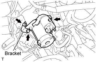
| 64. REMOVE STARTER ASSEMBLY (for Manual Transaxle) |
Disconnect the terminal 50 connector from the starter assembly.
 |
Remove the nut and disconnect the wire harness from terminal 30.
Remove the 3 bolts, clutch flexible hose bracket and starter assembly.
 |
| 65. REMOVE STARTER ASSEMBLY (for Automatic Transaxle) |
Disconnect the terminal 50 connector from the starter assembly.
 |
Remove the nut and disconnect the wire harness from terminal 30.
Remove the 2 bolts and starter assembly.
 |
| 66. SEPARATE AUTOMATIC TRANSAXLE ASSEMBLY (for Automatic Transaxle) |
- HINT:
| 67. SEPARATE MANUAL TRANSAXLE ASSEMBLY (for Manual Transaxle) |
- HINT:
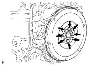
| 68. REMOVE DRIVE PLATE & RING GEAR SUB-ASSEMBLY (for Automatic Transaxle) |
Using SST, hold the crankshaft.
- SST
- 09213-54015(91651-60855)
09330-00021
 |
Remove the 8 bolts, rear spacer, drive plate and front spacer.
 |
| 69. REMOVE CLUTCH COVER ASSEMBLY (for Manual Transaxle) |
Put matchmarks on the clutch cover assembly and flywheel sub-assembly.
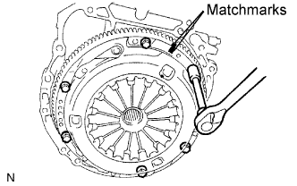 |
Loosen the 6 bolts one turn at a time until spring tension is released.
Remove the 6 bolts and pull off the clutch cover assembly.
- NOTICE:
- Do not drop the clutch disc assembly.
| 70. REMOVE CLUTCH DISC ASSEMBLY (for Manual Transaxle) |
- NOTICE:
- Keep the lining part of the clutch disc assembly, the pressure plate and surface of the flywheel sub-assembly away from oil and foreign matter.
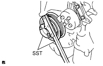
| 71. REMOVE FLYWHEEL SUB-ASSEMBLY (for Manual Transaxle) |
Using SST, hold the crankshaft.
- SST
- 09213-54015(91651-60855)
09330-00021
|
Remove the 8 bolts and flywheel.
 |
| 72. INSTALL ENGINE STAND |
Fix the engine onto a engine stand with the bolts.
| 73. REMOVE FUEL DELIVERY PIPE WITH INJECTOR |
Remove the 2 wire harness clamps.
 |
Disconnect the 4 fuel injector connectors.
Remove the 2 bolts, then remove the fuel delivery pipe together with the 4 fuel injectors.
- NOTICE:
- Be careful not to drop the fuel injectors when removing the fuel delivery pipe.
 |
Remove the 2 delivery pipe spacers from the cylinder head.
 |
Remove the 4 insulators from the cylinder head.
| 74. REMOVE INTAKE MANIFOLD |
Remove the 5 bolts, 2 nuts, and intake manifold.
 |
Remove the gasket from the intake manifold.
 |
| 75. REMOVE NO. 2 VENTILATION HOSE |
| 76. REMOVE NO. 1 INTAKE MANIFOLD INSULATOR |
Remove the intake manifold insulator from the cylinder block.
 |
| 77. REMOVE DRIVE SHAFT BEARING BRACKET |
Remove the 3 bolts and drive shaft bearing bracket.
 |
| 78. REMOVE OIL LEVEL GAUGE SUB-ASSEMBLY |
| 79. REMOVE OIL LEVEL GAUGE GUIDE |
Remove the bolt and oil level gauge guide.
 |
Remove the O-ring from the oil level gauge guide.
| 80. REMOVE MANIFOLD STAY |
Remove the bolt, nut and stay.
 |
| 81. REMOVE NO. 2 MANIFOLD STAY |
Remove the bolt, nut and stay.
 |
| 82. REMOVE EXHAUST MANIFOLD CONVERTER SUB-ASSEMBLY |
Remove the 4 bolts and No. 1 insulator.
 |
Disconnect the air-fuel ratio sensor connector.
 |
Remove the 5 nuts, manifold converter and gasket.
 |
| 83. REMOVE WATER INLET |
 |
Remove the 2 nuts and disconnect the water inlet from the cylinder block.
| 84. REMOVE THERMOSTAT |
Remove the gasket from the thermostat.
| 85. REMOVE NO. 1 WATER BY-PASS PIPE |
Remove the bolt, 2 nuts and No. 1 water by-pass pipe with the gasket.
 |
| 86. REMOVE OIL COOLER PIPE |
Remove the bolt, 2 nuts and oil cooler pipe with the gasket.
 |
| 87. REMOVE ENGINE MOUNTING BRACKET RH |
Remove the 3 bolts and engine mounting bracket RH.
 |
| 88. REMOVE V-RIBBED BELT TENSIONER ASSEMBLY |
Remove the bolt, nut and belt tensioner.
 |
| 89. REMOVE IGNITION COIL ASSEMBLY |
Remove the 4 bolts and 4 ignition coils.
| 90. REMOVE CAMSHAFT TIMING OIL CONTROL VALVE ASSEMBLY |
Disconnect the camshaft timing oil control valve assembly connector.
 |
Remove the bolt and camshaft timing oil control valve assembly.
| 91. REMOVE KNOCK SENSOR |
Disconnect the sensor connector.
Remove the nut and sensor.
| 92. REMOVE RADIO SETTING CONDENSER |
Remove the bolt and radio setting condenser.
 |
| 93. REMOVE ENGINE OIL PRESSURE SWITCH ASSEMBLY |
Using a 24 mm deep socket wrench, remove the engine oil pressure switch assembly.
 |
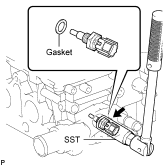
| 94. REMOVE ENGINE COOLANT TEMPERATURE SENSOR |
Using SST, remove the sensor and gasket.
- SST
- 09817-33190
 |