Sfi System Cranking Holding Function Circuit
DESCRIPTION
WIRING DIAGRAM
INSPECTION PROCEDURE
CHECK CRANKING
READ VALUE USING INTELLIGENT TESTER (STA SIGNAL)
INSPECT ECM (STSW VOLTAGE)
INSPECT ECM (STAR VOLTAGE)
INSPECT ST CUT RELAY
INSPECT PARK/NEUTRAL SWITCH ASSEMBLY
INSPECT STARTER RELAY
CHECK HARNESS AND CONNECTOR (PARK/NEUTRAL POSITION SWITCH - STARTER RELAY)
INSPECT ENGINE ROOM RELAY BLOCK (STARTER RELAY VOLTAGE)
INSPECT STARTER ASSEMBLY
CHECK HARNESS AND CONNECTOR (MAIN BODY ECU - ECM)
SFI SYSTEM - Cranking Holding Function Circuit |
DESCRIPTION
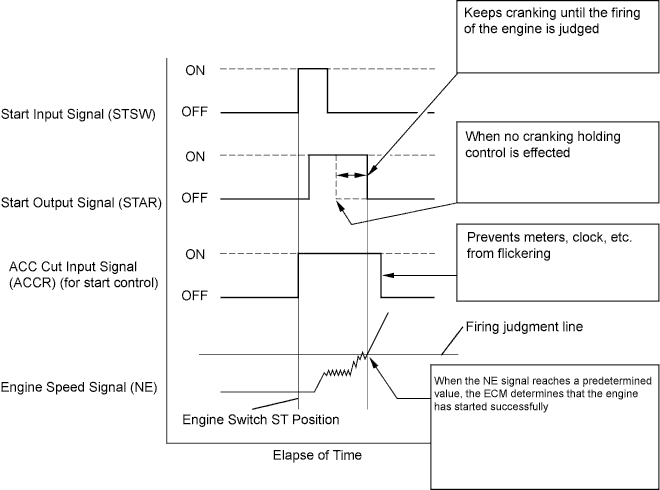
The cranking holding control system provides current to the starter when the ECM detects the engine switch start signal (STSW). When the ECM judges that the engine has started , the system cuts current to the starter. When the ECM receives the STSW signal, the ACC (Accessory) relay is turned off to prevent flickering of the combination meter, clock and audio system. Also, the STAR output signal travels through the ST cut relay and the park/neutral position switch assembly to the ST relay, causing the starter to activate. When the engine is cranking, the starter operation signal is received by the STA terminal of the ECM.
WIRING DIAGRAM
Refer to DTC P0617 (Link).
INSPECTION PROCEDURE
When starting the engine, check whether the starter motor starts.
| | CHECK FOR INTERMITTENT PROBLEMS |
|
|
| 2.READ VALUE USING INTELLIGENT TESTER (STA SIGNAL) |
Connect the intelligent tester to the DLC3.
Turn the engine switch on (IG).
Turn the intelligent tester on.
Select the following menu items: Powertrain / Engine / Data List / Starter Signal. Read the values.
Check the result when the engine switch is turned on (IG) and when the engine is started.
- Standard:
Display (Starter Signal)
| Condition
|
OFF
| Engine switch on (IG)
|
ON
| Engine start
|
| 3.INSPECT ECM (STSW VOLTAGE) |
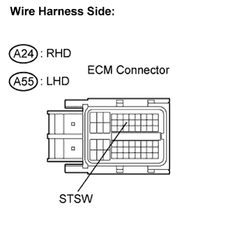
Disconnect the A24 (RHD) or A55 (LHD) ECM Connector.
Measure the voltage between the terminal of the ECM connector and body ground while cranking the engine.
- Standard voltage:
- RHD:
Tester Connection
| Specified Condition
|
STSW (A24-14) - Body ground
| 11 to 14 V
|
- LHD:
Tester Connection
| Specified Condition
|
STSW (A55-14) - Body ground
| 11 to 14 V
|
Reconnect the ECM connector.
| 4.INSPECT ECM (STAR VOLTAGE) |
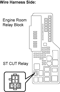
Remove the ST CUT relay from the engine room R/B.
Measure the voltage between the terminals of the engine room R/B and body ground while cranking the engine.
- Standard voltage:
Tester Connection
| Specified Condition
|
ST CUT relay (3) - Body ground
| 11 to 14 V
|
Reinstall the ST CUT relay.
Remove the ST CUT relay from the engine room R/B.
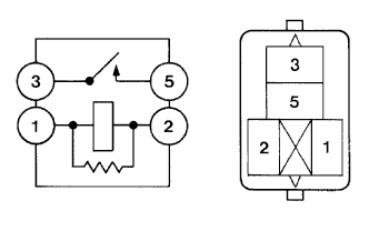
Measure the resistance between the terminals.
- Standard resistance:
Tester Connection
| Specified Condition
|
3 - 5
| 10 kΩ or higher
|
3 - 5
| Below 1 Ω
(when battery voltage applied between terminals 1 and 2)
|
Reinstall the ST CUT relay.
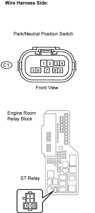
| 6.INSPECT PARK/NEUTRAL SWITCH ASSEMBLY |
Inspect the Park/Neutral Position (PNP) switch.
Disconnect the C1 switch connector.
Measure the resistance according to the value(s) in the table below.
- Standard resistance:
Gear Selector Lever Position
| Tester Connection
| Specified Condition
|
P
| 4 - 5
| Below 1 Ω
|
N
| 4 - 5
| Below 1 Ω
|
Reconnect the PNP switch connector.
| OK |
|
|
|
| CHECK HARNESS AND CONNECTOR |
|
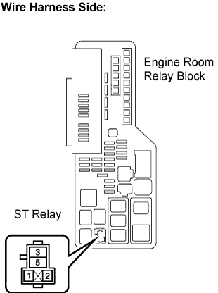
Remove the ST relay from the engine room R/B.
Measure the resistance between the terminals.
- Standard resistance:
Tester Connection
| Specified Condition
|
3 - 5
| 10 kΩ or higher
|
3 - 5
| Below 1 Ω
(when battery voltage applied between terminals 1 and 2)
|
Reinstall the ST relay.
| 8.CHECK HARNESS AND CONNECTOR (PARK/NEUTRAL POSITION SWITCH - STARTER RELAY) |
Disconnect the C1 park/neutral position switch connector.
Remove the ST relay from the engine room R/B.
Measure the resistance according to the value(s) in the table below.
- Standard resistance (Check for open):
Tester Connection
| Specified Condition
|
C1-9 - ST relay terminal (1)
| Below 1 Ω
|
- Standard resistance (Check for open):
Tester Connection
| Specified Condition
|
C1-9 or ST relay terminal (1) - Body ground
| 10 kΩ or higher
|
Reinstall the ST relay.
| | REPAIR OR REPLACE HARNESS OR CONNECTOR |
|
|
| 9.INSPECT ENGINE ROOM RELAY BLOCK (STARTER RELAY VOLTAGE) |
Remove the ST relay from the engine room R/B.
Measure the voltage between the terminals of the engine room R/B and body ground.
- Standard voltage:
Tester Connection
| Specified Condition
|
ST relay (5) - Body ground
| 11 to 14 V
|
| | REPAIR OR REPLACE HARNESS OR CONNECTOR |
|
|
| 10.INSPECT STARTER ASSEMBLY |
Inspect the starter assembly (CAMRY_ACV40 RM000000YQ201EX.html).
| | REPAIR OR REPLACE STARTER ASSEMBLY |
|
|
| OK |
|
|
|
| REPAIR OR REPLACE HARNESS OR CONNECTOR (STARTER RELAY - STARTER, STARTER - BATTERY) |
|
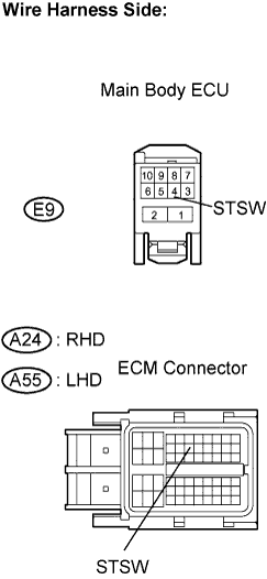
| 11.CHECK HARNESS AND CONNECTOR (MAIN BODY ECU - ECM) |
Disconnect the E9 main body ECU connector.
Disconnect the A24 (RHD) or A55 (LHD) ECM connector.
Measure the resistance according to the value(s) in the table below.
- Standard resistance (Check for open):
- RHD:
Tester Connection
| Specified Condition
|
STSW (E9-4) - STSW (A24-14)
| Below 1 Ω
|
- LHD:
Tester Connection
| Specified Condition
|
STSW (E9-4) - STSW (A55-14)
| Below 1 Ω
|
- Standard resistance (Check for short):
- RHD:
Tester Connection
| Specified Condition
|
STSW (E9-4) or STSW (A24-14) - Body ground
| 10 kΩ or higher
|
- LHD:
Tester Connection
| Specified Condition
|
STSW (E9-4) or STSW (A55-14) - Body ground
| 10 kΩ or higher
|
Reconnect the main body ECU connector.
Reconnect the ECM connector.
| | REPAIR OR REPLACE HARNESS OR CONNECTOR |
|
|