Crankshaft Position Sensor Installation
INSTALL CRANKSHAFT POSITION SENSOR
INSTALL GENERATOR ASSEMBLY
INSTALL V-RIBBED BELT
INSTALL FRONT FENDER APRON SEAL RH
INSTALL FRONT WHEEL RH
CONNECT CABLE TO NEGATIVE BATTERY TERMINAL
Crankshaft Position Sensor -- Installation |
| 1. INSTALL CRANKSHAFT POSITION SENSOR |
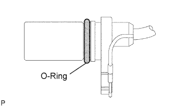
Apply a light coat of engine oil to the O-ring on the crankshaft position sensor.
Install the crankshaft position sensor with the bolt.
- Torque:
- 9.0 N*m{92 kgf*cm, 80 in.*lbf}
Connect the crankshaft position sensor connector.
| 2. INSTALL GENERATOR ASSEMBLY |
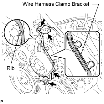
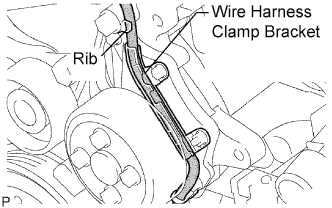
Confirm that the wire harness of the crankshaft position sensor is secured to the wire harness clamp bracket through the back of the rib of the timing chain cover.
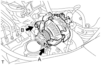
Install the generator assembly with the 2 bolts.
- Torque:
- Bolt A:
- 21 N*m{215 kgf*cm, 16 ft.*lbf}
- Bolt B:
- 52 N*m{530 kgf*cm, 38 ft.*lbf}
Install the generator wire to terminal B with the nut.
- Torque:
- 9.8 N*m{100 kgf*cm, 87 in.*lbf}
Install the clamp bracket with the bolt.
- Torque:
- 8.4 N*m{86 kgf*cm, 74 in.*lbf}
Attach the clamp and connect the generator connector to the generator.
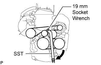
Using SST and 19 mm socket wrench, loosen the V-ribbed belt tensioner arm clockwise, then install the V-ribbed belt.
- SST
- 09216-42010
- NOTICE:
- Be sure to connect SST and the tools so that they are in line during use.
- When retracting the tensioner, turn it clockwise slowly for 3 seconds or more. Do not apply force rapidly.
- After the tensioner is fully retracted, do not apply force any more than necessary.
After installing the V-ribbed belt, check that it fits properly in the ribbed grooves. Check to confirm that the belt has not slipped out of the grooves on the bottom of the crank pulley by hand.
| 4. INSTALL FRONT FENDER APRON SEAL RH |
| 5. INSTALL FRONT WHEEL RH |
| 6. CONNECT CABLE TO NEGATIVE BATTERY TERMINAL |