READ VALUE USING INTELLIGENT TESTER (VEHICLE SPEED)
CHECK COMBINATION METER SYSTEM
CHECK HARNESS AND CONNECTOR (COMBINATION METER ASSEMBLY - ECM)
CHECK HARNESS AND CONNECTOR (ECM - NO. 3 JUNCTION BLOCK)
DTC P0500 Vehicle Speed Sensor "A" |
DESCRIPTION
The wheel speed sensor monitors the wheel rotation speed and sends a signal to the skid control ECU. The skid control ECU converts the wheel speed signal into a 4-pulse signal and transmits it to the ECM via the combination meter. The ECM determines the vehicle speed based on the frequency of the pulse signal.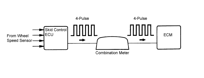
| DTC No. | DTC Detection Condition | Trouble Area |
| P0500 | While vehicle being driven, no vehicle speed sensor signal to ECM. (1 trip detection logic: Automatic transaxle) (2 trip detection logic: Manual transaxle) |
|
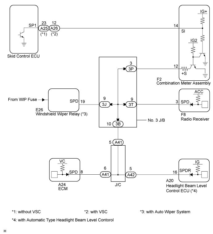
WIRING DIAGRAM
INSPECTION PROCEDURE
- HINT:
- Read freeze frame data using the intelligent tester. The ECM records vehicle and driving condition information as freeze frame data the moment a DTC is stored. When troubleshooting, freeze frame data can help determine if the vehicle was moving or stationary, if the engine was warmed up or not, if the air-fuel ratio was lean or rich, and other data from the time the malfunction occurred.
| 1.READ VALUE USING INTELLIGENT TESTER (VEHICLE SPEED) |
Connect the intelligent tester to the DLC3.
Turn the ignition switch to the ON position.
Turn the tester on.
Select the following menu items: Powertrain / Engine and ECT / Date List / Vehicle Speed.
Drive the vehicle.
Read the value displayed on the tester.
- OK:
- Vehicle speeds displayed on tester and speedometer display are equal.
|
| ||||
| OK | ||
| ||
| 2.CHECK COMBINATION METER SYSTEM |
The circuits that send vehicle speed signals to this system are inspected in the meter system (CAMRY_ACV40 RM000002UD700KX.html).
During inspection for the meter section, if there is an instruction that indicates to go back inspections for each system, proceed to the next step.
| NEXT | |
| 3.CHECK HARNESS AND CONNECTOR (COMBINATION METER ASSEMBLY - ECM) |
Disconnect the A24 ECM connector.
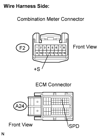 |
Disconnect the F2 combination meter connector.
Measure the resistance according to the value(s) in the table below.
- Standard resistance (Check for open):
Tester Connection Condition Specified Condition +S (F2-12) - SPD (A24-8) Always Below 1 Ω
Reconnect the ECM connector.
Reconnect the combination meter connector.
|
| ||||
| OK | ||
| ||
| 4.CHECK HARNESS AND CONNECTOR (ECM - NO. 3 JUNCTION BLOCK) |
Disconnect the A24 ECM connector.
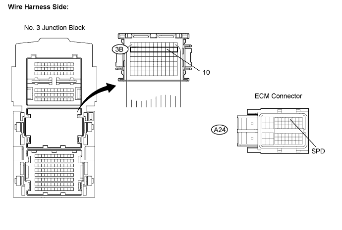
Disconnect the 3B No. 3 junction block connector.
Measure the resistance according to the value(s) in the table below.
- Standard resistance (Check for open):
Tester Connection Condition Specified Condition 3B-10 - SPD (A24-8) Always Below 1 Ω
Reconnect the ECM connector.
Reconnect the No. 3 junction block connector.
|
| ||||
| OK | ||
| ||