Can Communication System Combination Meter Ecu Communication Stop Mode
DESCRIPTION
WIRING DIAGRAM
INSPECTION PROCEDURE
CHECK HARNESS AND CONNECTOR (COMBINATION METER ECU - BATTERY AND BODY GROUND)
CAN COMMUNICATION SYSTEM - Combination Meter ECU Communication Stop Mode |
DESCRIPTION
Detection Item
| Symptom
| Trouble Area
|
Combination Meter ECU Communication Stop Mode
| Either condition is met:
- "Combination Meter" is not displayed on "Bus Check".
- Applies to "Combination Meter ECU Communication Stop Mode" in "DTC Combination Table" applies.
| - Power source or inside combination meter ECU
- Harness or connector
- Combination meter ECU
|
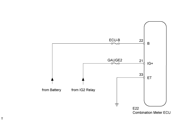
WIRING DIAGRAM
INSPECTION PROCEDURE
| 1.CHECK HARNESS AND CONNECTOR (COMBINATION METER ECU - BATTERY AND BODY GROUND) |
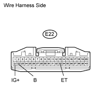
Disconnect the E22 combination meter ECU connector.
Measure the resistance according to the value(s) in the table below.
- Standard Resistance:
Tester Connection
| Condition
| Specified Condition
|
E22-33 (ET) - Body ground
| Always
| Below 1 Ω
|
Measure the voltage according to the value(s) in the table below.
- Standard Voltage:
Tester Connection
| Switch Condition
| Specified Condition
|
E22-22 (B) - Body ground
| Always
| 11 to 14 V
|
E22-21 (IG+) - Body ground
| Ignition switch on (IG)
| 11 to 14 V
|
| | REPAIR OR REPLACE HARNESS OR CONNECTOR |
|
|
| OK |
|
|
|
| REPLACE COMBINATION METER ECU |
|