Center Power Outlet Socket Removal
DISCONNECT CABLE FROM NEGATIVE BATTERY TERMINAL
REMOVE NO. 1 CONSOLE UPPER PANEL GARNISH
REMOVE NO. 2 CONSOLE UPPER PANEL GARNISH
REMOVE SHIFT LEVER KNOB SUB-ASSEMBLY
REMOVE UPPER CONSOLE PANEL SUB-ASSEMBLY (for Manual Transaxle)
REMOVE FLOOR SHIFT POSITION INDICATOR HOUSING SUB-ASSEMBLY (for Automatic Transaxle)
REMOVE UPPER REAR CONSOLE PANEL SUB-ASSEMBLY
REMOVE CENTER POWER OUTLET SOCKET ASSEMBLY
Center Power Outlet Socket -- Removal |
| 1. DISCONNECT CABLE FROM NEGATIVE BATTERY TERMINAL |
- CAUTION:
- Wait at least 90 seconds after disconnecting the cable from the negative (-) battery terminal to prevent airbag and seat belt pretensioner activation.
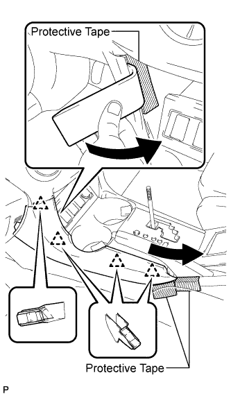
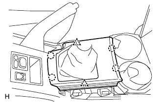
| 2. REMOVE NO. 1 CONSOLE UPPER PANEL GARNISH |
Place protective tape as shown in the illustration.
Using a moulding remover, detach the 4 clips and remove the upper panel garnish.
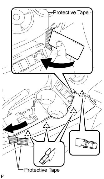
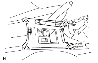
| 3. REMOVE NO. 2 CONSOLE UPPER PANEL GARNISH |
Place protective tape as shown in the illustration.
Using a moulding remover, detach the 4 clips and remove the upper panel garnish.
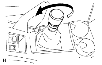
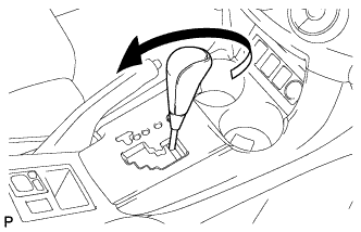
| 4. REMOVE SHIFT LEVER KNOB SUB-ASSEMBLY |
for Manual Transaxle:
Twist the shift lever knob in the direction indicated by the arrow and remove it.
for Automatic Transaxle:
Twist the shift lever knob in the direction indicated by the arrow and remove it.
| 5. REMOVE UPPER CONSOLE PANEL SUB-ASSEMBLY (for Manual Transaxle) |
Using a screwdriver, detach the 2 clips and 4 claws, and then remove the upper console panel.
- HINT:
- Tape the screwdriver tip before use.
| 6. REMOVE FLOOR SHIFT POSITION INDICATOR HOUSING SUB-ASSEMBLY (for Automatic Transaxle) |
Using a screwdriver, detach the 2 clips and 4 claws, and then remove the floor shift position indicator housing.
- HINT:
- Tape the screwdriver tip before use.
Disconnect the connector.
| 7. REMOVE UPPER REAR CONSOLE PANEL SUB-ASSEMBLY |
Using a screwdriver, detach the 4 clips.
- HINT:
- Tape the screwdriver tip before use.
Disconnect the connectors and remove the upper rear console panel.
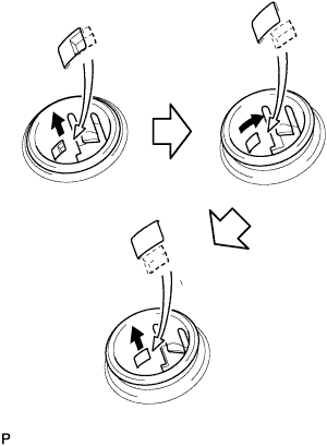
| 8. REMOVE CENTER POWER OUTLET SOCKET ASSEMBLY |
Rotate the socket to disengage the notch.
Pull out the socket halfway and rotate the socket until its protrusion is aligned with the groove of the cover.
Remove the socket from the cover.