Rear View Monitor System (W/ Navigation System) Display Signal Circuit Between Navigation Receiver Assembly And Television Camera Assembly
DESCRIPTION
WIRING DIAGRAM
INSPECTION PROCEDURE
CHECK NAVIGATION RECEIVER ASSEMBLY
CHECK TELEVISION CAMERA ASSEMBLY
CHECK HARNESS AND CONNECTOR (NAVIGATION RECEIVER ASSEMBLY - TELEVISION CAMERA ASSEMBLY)
REAR VIEW MONITOR SYSTEM (w/ Navigation System) - Display Signal Circuit between Navigation Receiver Assembly and Television Camera Assembly |
DESCRIPTION
This is the display signal circuit of the television camera.
WIRING DIAGRAM
INSPECTION PROCEDURE
| 1.CHECK NAVIGATION RECEIVER ASSEMBLY |
for 3ZR-FAE:
Measure the voltage according to the value(s) in the table below.
- Standard Voltage:
Tester Connection
| Switch Condition
| Specified Condition
|
E106-2 (CA+) - E106-12 (CGND)
| Ignition switch ON, shift lever in R
| 5.5 to 7.05 V
|
except 3ZR-FAE:
Measure the voltage according to the value(s) in the table below.
- Standard Voltage:
Tester Connection
| Switch Condition
| Specified Condition
|
E54-24 (CA+) - E54-21 (CGND)
| Ignition switch ON, shift lever in R
| 5.5 to 7.05 V
|
ResultResult
| Proceed to
|
OK
| A
|
NG (for HDD Navigation System)
| B
|
NG (for DVD Navigation System)
| C
|
| 2.CHECK TELEVISION CAMERA ASSEMBLY |
for 3ZR-FAE:
Using an oscilloscope, check the waveform.
Measurement ConditionItem
| Content
|
Tester Connection
| E106-1 (V+) - E106-11 (V-)
|
Tool Setting
| 0.2 V/DIV., 50 μs/DIV.
|
Condition
| - Ignition switch ON, shift lever in R*1
- Ignition switch ON, shift lever in R, screen blacked out by covering camera lens*2
|
- OK:
- Waveform is as shown in illustration.
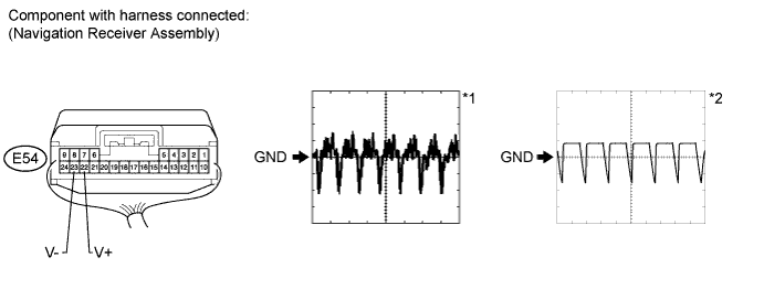
except 3ZR-FAE:
Using an oscilloscope, check the waveform.
Measurement ConditionItem
| Content
|
Tester Connection
| E54-23 (V+) - E54-22 (V-)
|
Tool Setting
| 0.2 V/DIV., 50 μs/DIV.
|
Condition
| - Ignition switch ON, shift lever in R*1
- Ignition switch ON, shift lever in R, screen blacked out by covering camera lens*2
|
- OK:
- Waveform is as shown in illustration.
| 3.CHECK HARNESS AND CONNECTOR (NAVIGATION RECEIVER ASSEMBLY - TELEVISION CAMERA ASSEMBLY) |
for 3ZR-FAE:
Disconnect the E106 navigation receiver assembly connector.
Disconnect the S7 camera assembly connector.
Measure the resistance according to the value(s) in the table below.
- Standard Resistance:
Tester Connection
| Condition
| Specified Condition
|
E106-2 (CA+) - S7-4 (CB+)
| Always
| Below 1 Ω
|
E106-12 (CGND) - S7-3 (CGND)
| Always
| Below 1 Ω
|
E106-1 (V+) - S7-2 (CV+)
| Always
| Below 1 Ω
|
E106-11 (V-) - S7-1 (CV-)
| Always
| Below 1 Ω
|
E106-2 (CA+) - Body ground
| Always
| 10 kΩ or higher
|
E106-12 (CGND) - Body ground
| Always
| 10 kΩ or higher
|
E106-1 (V+) - Body ground
| Always
| 10 kΩ or higher
|
E106-11 (V-) - Body ground
| Always
| 10 kΩ or higher
|
except 3ZR-FAE:
Disconnect the E54 navigation receiver assembly connector.
Disconnect the S7 camera assembly connector.
Measure the resistance according to the value(s) in the table below.
- Standard Resistance:
Tester Connection
| Condition
| Specified Condition
|
E54-24 (CA+) - S7-4 (CB+)
| Always
| Below 1 Ω
|
E54-21 (CGND) - S7-3 (CGND)
| Always
| Below 1 Ω
|
E54-22 (V+) - S7-2 (CV+)
| Always
| Below 1 Ω
|
E54-23 (V-) - S7-1 (CV-)
| Always
| Below 1 Ω
|
E54-24 (CA+) - Body ground
| Always
| 10 kΩ or higher
|
E54-21 (CGND) - Body ground
| Always
| 10 kΩ or higher
|
E54-22 (V+) - Body ground
| Always
| 10 kΩ or higher
|
E54-23 (V-) - Body ground
| Always
| 10 kΩ or higher
|
| | REPAIR OR REPLACE HARNESS OR CONNECTOR |
|
|