Audio And Visual System Microphone Circuit Between Microphone And Radio Receiver
DESCRIPTION
WIRING DIAGRAM
INSPECTION PROCEDURE
INSPECT RADIO RECEIVER ASSEMBLY
CHECK HARNESS AND CONNECTOR (OVERHEAD JUNCTION BLOCK [MICROPHONE] - RADIO RECEIVER)
AUDIO AND VISUAL SYSTEM - Microphone Circuit between Microphone and Radio Receiver |
DESCRIPTION
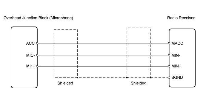
This circuit sends a microphone signal from the microphone to the radio receiver. It also supplies power from the radio receiver to the microphone.
WIRING DIAGRAM
INSPECTION PROCEDURE
| 1.INSPECT RADIO RECEIVER ASSEMBLY |
Measure the voltage according to the value(s) in the table below.
- Standard Voltage:
Tester Connection
| Switch Condition
| Specified Condition
|
3 (MACC) - Body ground
| Ignition switch on (ACC)
| 4 to 6 V
|
| | REPLACE RADIO RECEIVER ASSEMBLY |
|
|
| 2.CHECK HARNESS AND CONNECTOR (OVERHEAD JUNCTION BLOCK [MICROPHONE] - RADIO RECEIVER) |
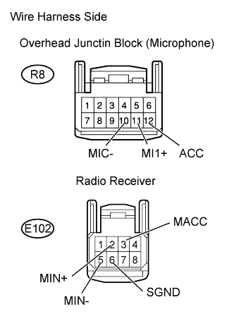
Disconnect the R8 overhead junction block (microphone) and E102 radio receiver connectors.
Measure the resistance according to the value(s) in the table below.
- Standard Resistance:
Tester Connection
| Specified Condition
|
E102-3 (MACC) - R8-12 (ACC)
| Below 1 Ω
|
E102-2 (MIN+) - R8-11 (MI1+)
| Below 1 Ω
|
E102-5 (MIN-) - R8-10 (MIC-)
| Below 1 Ω
|
E102-3 (MACC) - Body ground
| 10 kΩ or higher
|
E102-2 (MIN+) - Body ground
| 10 kΩ or higher
|
E102-5 (MIN-) - Body ground
| 10 kΩ or higher
|
E102-6 (SGND) - Body ground
| 10 kΩ or higher
|
| | REPAIR OR REPLACE HARNESS OR CONNECTOR |
|
|
| OK |
|
|
|
| PROCEED TO NEXT CIRCUIT INSPECTION SHOWN IN PROBLEM SYMPTOMS TABLE |
|