Audio And Visual System Speaker Circuit
DESCRIPTION
WIRING DIAGRAM
INSPECTION PROCEDURE
CHECK SPEAKER
CHECK FRONT NO. 2 SPEAKER ASSEMBLY
INSPECT FRONT NO. 2 SPEAKER ASSEMBLY
CHECK WIRE HARNESS (FRONT NO. 1 SPEAKER - FRONT NO. 2 SPEAKER)
CHECK WIRE HARNESS (RADIO RECEIVER - FRONT NO. 2 SPEAKER)
INSPECT FRONT NO. 2 SPEAKER ASSEMBLY
CHECK WIRE HARNESS (RADIO RECEIVER - REAR NO. 1 SPEAKER)
INSPECT REAR NO. 1 SPEAKER ASSEMBLY
AUDIO AND VISUAL SYSTEM - Speaker Circuit |
DESCRIPTION
The radio receiver sends sound signals to the speakers.
WIRING DIAGRAM
INSPECTION PROCEDURE
Check that the speaker sounds.
ResultResult
| Proceed to
|
Front No. 1 speaker does not operate
| A
|
Front No. 2 speaker does not operate
| B
|
Rear No. 1 speaker does not operate
| C
|
All speakers do not operate
| D
|
| |
|
| |
|
| | PROCEED TO NEXT INSPECTION PROCEDURE SHOWN IN PROBLEM SYMPTOMS TABLE |
|
|
| 2.CHECK FRONT NO. 2 SPEAKER ASSEMBLY |
Check that the front No. 2 speaker sounds.
- OK:
- Speaker sounds.
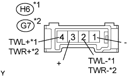
| 3.INSPECT FRONT NO. 2 SPEAKER ASSEMBLY |
Disconnect the H6 or G7 receiver connector.
Measure the resistance of the speaker.
- Standard resistance:
Tester Connection
| Specified Condition
|
1 (-) - 2 (TWL-)*1 or (TWR-)*2
| Below 1 Ω
|
3 (+) - 4 (TWL+)*1 or (TWR+)*2
| Below 1 Ω
|
1 (-) - Body ground
| 10 kΩ or higher
|
3 (+) - Body ground
| 10 kΩ or higher
|
- HINT:
- *1: for LH
- *2: for RH
| | REPLACE FRONT NO. 2 SPEAKER ASSEMBLY |
|
|
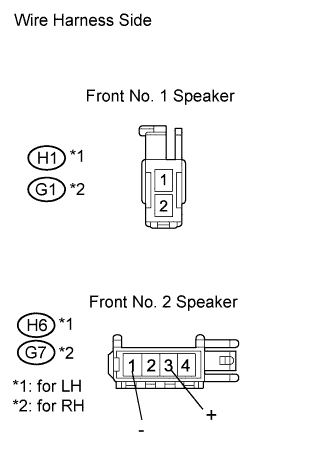
| 4.CHECK WIRE HARNESS (FRONT NO. 1 SPEAKER - FRONT NO. 2 SPEAKER) |
Disconnect the H1 and H6, or G1 and G7 connectors.
Measure the resistance of the wire harness side connectors.
- Standard resistance:
Tester Connection
| Specified Condition
|
H1-1 - H6-3 (+)
| Below 1 Ω
|
H1-1 - Body ground
| 10 kΩ or higher
|
H1-2 - H6-1 (-)
| Below 1 Ω
|
H1-2 - Body ground
| 10 kΩ or higher
|
G1-1 - G7-3 (+)
| Below 1 Ω
|
G1-1 - Body ground
| 10 kΩ or higher
|
G1-2 - G7-1 (-)
| Below 1 Ω
|
G1-2 - Body ground
| 10 kΩ or higher
|
| | REPAIR OR REPLACE HARNESS AND CONNECTOR |
|
|
| OK |
|
|
|
| REPLACE FRONT NO. 1 SPEAKER ASSEMBLY |
|
| 5.CHECK WIRE HARNESS (RADIO RECEIVER - FRONT NO. 2 SPEAKER) |
Disconnect the E90 receiver connector.
Disconnect the H6 or G7 speaker connector.
Measure the resistance of the wire harness side connectors.
- Standard resistance:
Tester Connection
| Specified Condition
|
E90-1 (FR+) - G7-4 (TWR+)
| Below 1 Ω
|
E90-5 (FR-) - G7-2 (TWR-)
| Below 1 Ω
|
E90-1 (FR+) - Body ground
| 10 kΩ or higher
|
E90-5 (FR-) - Body ground
| 10 kΩ or higher
|
E90-2 (FL+) - H6-4 (TWL+)
| Below 1 Ω
|
E90-6 (FL-) - H6-2 (TWL-)
| Below 1 Ω
|
E90-2 (FL+) - Body ground
| 10 kΩ or higher
|
E90-6 (FL-) - Body ground
| 10 kΩ or higher
|
| | REPAIR OR REPLACE HARNESS AND CONNECTOR |
|
|
| 6.INSPECT FRONT NO. 2 SPEAKER ASSEMBLY |
Check that the malfunction disappears when another speaker in good condition is installed.
- OK:
- Malfunction disappears.
- HINT:
- Connect all connectors to the speakers.
- When there is a possibility that either the right or left front speaker is defective, inspect by interchanging the right one with the left one.
| | REPLACE FRONT NO. 2 SPEAKER ASSEMBLY |
|
|
| NG |
|
|
|
| PROCEED TO NEXT INSPECTION PROCEDURE SHOWN IN PROBLEM SYMPTOMS TABLE |
|
| 7.CHECK WIRE HARNESS (RADIO RECEIVER - REAR NO. 1 SPEAKER) |
Disconnect the E91 receiver connector.
Disconnect the J2 or I2 receiver connector.
Measure the resistance of the wire harness side connectors.
- Standard resistance:
Tester Connection
| Specified Condition
|
E91-1 (RR+) - I2-1
| Below 1 Ω
|
E91-3 (RR-) - I2-2
| Below 1 Ω
|
E91-1 (RR+) - Body ground
| 10 kΩ or higher
|
E91-3 (RR-) - Body ground
| 10 kΩ or higher
|
E91-2 (RL+) - J2-1
| Below 1 Ω
|
E91-6 (RL-) - J2-2
| Below 1 Ω
|
E91-2 (RL+) - Body ground
| 10 kΩ or higher
|
E91-6 (RL-) - Body ground
| 10 kΩ or higher
|
| | REPAIR OR REPLACE HARNESS AND CONNECTOR |
|
|
| 8.INSPECT REAR NO. 1 SPEAKER ASSEMBLY |
Check the rear No. 1 speaker (RAV4_ACA30 RM0000011Q2009X.html).
- OK:
- Rear No. 1 speaker is normal.
| | REPLACE REAR NO. 1 SPEAKER ASSEMBLY |
|
|
| OK |
|
|
|
| PROCEED TO NEXT INSPECTION PROCEDURE SHOWN IN PROBLEM SYMPTOMS TABLE |
|