Meter / Gauge System Fuel Receiver Gauge Malfunction
Meter. Toyota Rav4. Aca30, 33, 38 Gsa33 Zsa30, 35
DESCRIPTION
WIRING DIAGRAM
INSPECTION PROCEDURE
PERFORM ACTIVE TEST USING INTELLIGENT TESTER (Fuel Meter Operation)
READ VALUE USING DATA LIST (Fuel Input (A/D))
INSPECT FUEL SENDER GAUGE ASSEMBLY
CHECK WIRE HARNESS (COMBINATION METER - FUEL SENDER GAUGE)
METER / GAUGE SYSTEM - Fuel Receiver Gauge Malfunction |
DESCRIPTION
The combination meter assembly controls the fuel receiver gauge in accordance with the resistance of the fuel sender gauge that varies depending on the amount of fuel remaining in the fuel tank.
WIRING DIAGRAM
INSPECTION PROCEDURE
| 1.PERFORM ACTIVE TEST USING INTELLIGENT TESTER (Fuel Meter Operation) |
Connect the intelligent tester to the DLC3.
Turn the ignition switch on (IG) and turn the tester ON.
Perform the ACTIVE TEST according to the prompts displayed on the tester.
Combination meterTester Display
| Test Part
| Control Range
|
Fuel Meter Operation
| EMPTY / 1/2 / FULL
| Value selected during Active Test is displayed
|
- OK:
- Value selected during Active Test is displayed.
| | REPLACE COMBINATION METER ASSEMBLY |
|
|
| 2.READ VALUE USING DATA LIST (Fuel Input (A/D)) |
Connect the intelligent tester to the DLC3.
Turn the ignition switch on (IG) and the tester ON.
Read the Data List according to the prompts displayed on the tester.
Combination meterTester Display
| Measurement Item/Range
| Normal Condition
| Diagnostic Note
|
Fuel Input (A/D)
| Fuel input signal / Min.: 0, Max.: 255
| Fuel gauge indicates (F): 33
Fuel gauge indicates (3/4): 98
Fuel gauge indicates (1/2): 144
Fuel gauge indicates (1/4): 179
Fuel gauge indicates (E): 206
| -
|
- OK:
- Meter / gauge value and tester value are the same.
| | REPLACE COMBINATION METER ASSEMBLY |
|
|
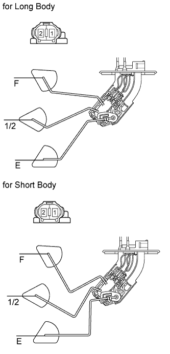
| 3.INSPECT FUEL SENDER GAUGE ASSEMBLY |
Remove the fuel sender gauge.
Measure the resistance of the gauge.
- Standard resistance:
Tester Connection
| Float Level
| Specified Condition
|
1 - 2
| F
| 15.0 +-1.5 Ω
|
1 - 2
| 1/2
| 212.5 +-12.2 Ω
|
1 - 2
| E
| 410.0 +-4.5 Ω
|
| | REPLACE FUEL SENDER GAUGE ASSEMBLY |
|
|
| 4.CHECK WIRE HARNESS (COMBINATION METER - FUEL SENDER GAUGE) |
Disconnect the E22 meter connector.
Disconnect the T2 gauge connector.
Measure the resistance of the wire harness side connectors.
- Standard resistance:
Tester Connection
| Specified Condition
|
E22-24 (L) - T2-1 (FS)
| Below 1 Ω
|
E22-12 (E) - T2-2 (FE)
| Below 1 Ω
|
E22-24 (L) or T2-1 (FS) - Body ground
| 10 kΩ or higher
|
E22-12 (E) or T2-2 (FE) - Body ground
| 10 kΩ or higher
|
| | REPAIR OR REPLACE HARNESS AND CONNECTOR |
|
|
| OK |
|
|
|
| REPLACE COMBINATION METER ASSEMBLY |
|