Lighting System Footwell Light Circuit
Lighting. Toyota Rav4. Aca30, 33, 38 Gsa33 Zsa30, 35
DESCRIPTION
WIRING DIAGRAM
INSPECTION PROCEDURE
PERFORM ACTIVE TEST USING INTELLIGENT TESTER (MAIN BODY ECU)
INSPECT FUSE (DOME)
INSPECT FOOT LIGHT
CHECK WIRE HARNESS (BATTERY - MAIN BODY ECU)
LIGHTING SYSTEM - Footwell Light Circuit |
DESCRIPTION
The main body ECU receives information regarding the door lock position switch and ignition switch, and turns on each foot light.
WIRING DIAGRAM
INSPECTION PROCEDURE
| 1.PERFORM ACTIVE TEST USING INTELLIGENT TESTER (MAIN BODY ECU) |
Connect the intelligent tester to the DLC3.
Turn the ignition switch on (IG) and press the intelligent tester main switch ON.
Select the item below in the ACTIVE TEST and then check the relay operates.
Main body ECUItem
| Test Details
| Diagnostic Note
|
Step Light
| Foot light ON/OFF
| -
|
- OK:
- Headlights (LOW) come on.
| | PROCEED TO NEXT CIRCUIT INSPECTION SHOWN IN PROBLEM SYMPTOMS TABLE |
|
|
Remove the DOME fuse from the engine room No. 2 relay block.
Measure the resistance of the fuse.
- Standard resistance:
- Below 1 Ω
Remove the foot light.
Connect the positive (+) lead from the battery to terminal 2 and the negative (-) lead to terminal 1, then check that the light comes on.
- OK:
- Light comes on.
| | REPLACE FOOT LIGHT ASSEMBLY |
|
|
| 4.CHECK WIRE HARNESS (BATTERY - MAIN BODY ECU) |
Connect the foot light.
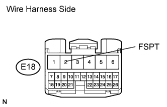
Disconnect the E18 main body ECU connector.
Measure the voltage of the wire harness side connector.
- Standard voltage:
Tester Connection
| Specified Condition
|
E18-2 (FSPT) - Body ground
| 10 to 14 V
|
| | REPAIR OR REPLACE HARNESS AND CONNECTOR |
|
|
| OK |
|
|
|
| REPLACE INSTRUMENT PANEL JUNCTION BLOCK (MAIN BODY ECU) |
|