Lighting System Headlight Relay Circuit
Lighting. Toyota Rav4. Aca30, 33, 38 Gsa33 Zsa30, 35
DESCRIPTION
WIRING DIAGRAM
INSPECTION PROCEDURE
PERFORM ACTIVE TEST USING INTELLIGENT TESTER (MAIN BODY ECU)
CHECK WIRE HARNESS (DIMMER SWITCH - MAIN BODY ECU AND BODY GROUND)
INSPECT HEADLIGHT DIMMER SWITCH
INSPECT FUSE (HEAD LL, HEAD RL)
INSPECT HEADLIGHT RELAY
INSPECT BULB (HEADLIGHT BULB)
CHECK VEHICLE CONDITION
CHECK HEADLIGHT UNIT
CHECK WIRE HARNESS (MAIN BODY ECU - BATTERY)
CHECK INSTRUMENT PANEL JUNCTION BLOCK (MAIN BODY ECU)
LIGHTING SYSTEM - Headlight Relay Circuit |
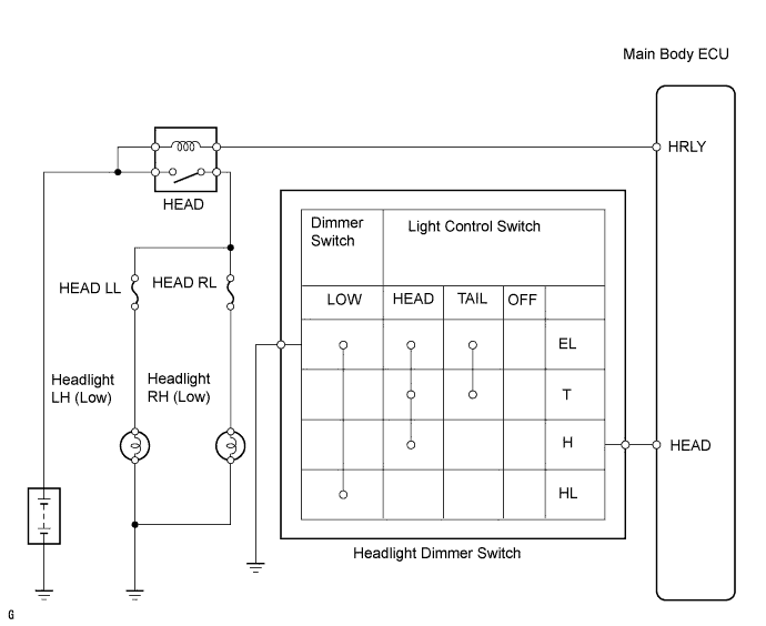
DESCRIPTION
When the light control switch, located on the headlight dimmer switch, is turned to the HEAD position, the headlight relay illuminates the headlights.
WIRING DIAGRAM
INSPECTION PROCEDURE
| 1.PERFORM ACTIVE TEST USING INTELLIGENT TESTER (MAIN BODY ECU) |
Connect the intelligent tester to the DLC3.
Turn the ignition switch on (IG) and press the intelligent tester main switch ON.
Select the item below in the ACTIVE TEST and then check that the relay operates.
- Main body ECU:
Item
| Test Details: Display (Range)
| Diagnostic Note
|
Head Light
| Headlight Relay ON/OFF
| -
|
- OK:
- Headlights (Low) come on
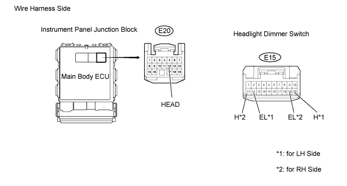
| 2.CHECK WIRE HARNESS (DIMMER SWITCH - MAIN BODY ECU AND BODY GROUND) |
Disconnect the E20 main body ECU connector.
Disconnect the E15 headlight dimmer switch connector.
Measure the resistance of the wire harness side connectors.
- Standard resistance:
for LH sideTester Connection
| Specified Condition
|
E20-12 (HEAD) - E15-20 (H)
| Below 1 Ω
|
E15-12 (EL) - Body ground
| Below 1 Ω
|
E20-12 (HEAD) - Body ground
| 10 kΩ or higher
|
for RH sideTester Connection
| Specified Condition
|
E20-12 (HEAD) - E15-11 (H)
| Below 1 Ω
|
E15-19 (EL) - Body ground
| Below 1 Ω
|
E20-12 (HEAD) - Body ground
| 10 kΩ or higher
|
| | REPAIR OR REPLACE HARNESS AND CONNECTOR |
|
|
| 3.INSPECT HEADLIGHT DIMMER SWITCH |
Remove the headlight dimmer switch.
Measure the resistance of the switch.
- Standard resistance:
for LH sideTester Connection
| Switch Condition
| Specified Condition
|
18 (T) - 12 (EL)
| Light control switch TAIL
| Below 1 Ω
|
18 (T) - 12 (EL)
| Light control switch OFF
| 10 kΩ or higher
|
20 (H) - 12 (EL)
| Light control switch HEAD
| Below 1 Ω
|
20 (H) - 12 (EL)
| Light control switch OFF
| 10 kΩ or higher
|
16 (HL) - 12 (EL)
| Dimmer switch LOW
| Below 1 Ω
|
16 (HL) - 12 (EL)
| Dimmer switch HIGH
| 10 kΩ or higher
|
for RH sideTester Connection
| Switch Condition
| Specified Condition
|
13 (T) - 19 (EL)
| Light control switch TAIL
| Below 1 Ω
|
13 (T) - 19 (EL)
| Light control switch OFF
| 10 kΩ or higher
|
11 (H) - 19 (EL)
| Light control switch HEAD
| Below 1 Ω
|
11 (H) - 19 (EL)
| Light control switch OFF
| 10 kΩ or higher
|
15 (HL) - 19 (EL)
| Dimmer switch LOW
| Below 1 Ω
|
15 (HL) - 19 (EL)
| Dimmer switch HIGH
| 10 kΩ or higher
|
| | REPLACE HEADLIGHT DIMMER SWITCH ASSEMBLY |
|
|
| OK |
|
|
|
| PROCEED TO NEXT CIRCUIT INSPECTION SHOWN IN PROBLEM SYMPTOMS TABLE |
|
| 4.INSPECT FUSE (HEAD LL, HEAD RL) |
Remove the HEAD LL fuse and HEAD RL fuse from the engine room No. 2 relay block.
Measure the resistance of the fuses.
- Standard resistance:
- Below 1 Ω
| 5.INSPECT HEADLIGHT RELAY |
Remove the headlight relay from the engine room No. 2 relay block.
Measure the resistance of the relay.
- Standard resistance:
Tester Connection
| Specified Condition
|
3 - 5
| 10 kΩ or higher
|
3 - 5
| Below 1 Ω
(Battery voltage applied to terminals 1 and 2)
|
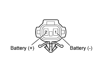
| 6.INSPECT BULB (HEADLIGHT BULB) |
Remove the headlight bulbs.
Connect the positive (+) lead from the battery to terminal 2 and the negative (-) lead to terminal 1, then check that the bulb illuminates.
- OK:
- Bulb illuminates.
| 7.CHECK VEHICLE CONDITION |
Check the vehicle condition.
ResultResult
| Proceed to
|
w/ Hood Moulding
| A
|
w/o Hood Moulding
| B
|
Disconnect the A73 (for LH) and A78 (for RH) headlight (Low) connectors.
Connect the positive (+) lead from the battery to terminal 2 and the negative (-) lead to terminal 1, then check that the headlights (Low) come on.
- OK:
- Headlights (Low) come on.
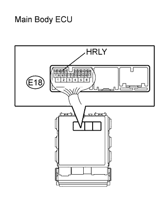
| 9.CHECK WIRE HARNESS (MAIN BODY ECU - BATTERY) |
Disconnect the E18 main body ECU connector.
Measure the voltage of the wire harness side connector.
- Standard voltage:
Tester Connection
| Specified Condition
|
E18-20 (HRLY) - Body ground
| 11 to 14 V
|
| | REPAIR OR REPLACE HARNESS AND CONNECTOR |
|
|
| 10.CHECK INSTRUMENT PANEL JUNCTION BLOCK (MAIN BODY ECU) |
Measure the voltage of the ECU.
- Standard voltage:
Tester Connection
| Condition
| Specified Condition
|
E18-20 (HRLY) - Body ground
| Light control switch OFF
| 11 to 14 V
|
E18-20 (HRLY) - Body ground
| Light control switch HEAD
| Below 1 V
|
| | REPLACE INSTRUMENT PANEL JUNCTION BLOCK (MAIN BODY ECU) |
|
|
| OK |
|
|
|
| REPAIR OR REPLACE HARNESS AND CONNECTOR (HEADLIGHT RELAY - HEADLIGHT BULB AND BODY GROUND) |
|