Dtc B2271 Ignition Hold Monitor Malfunction
Lexus IS250 IS220d GSE20 ALE20 4GR-FSE STARTING
DESCRIPTION
WIRING DIAGRAM
INSPECTION PROCEDURE
INSPECT FUSE (AM2)
CHECK CONNECTORS
CHECK WIRE HARNESS (POWER SOURCE CONTROL ECU - BATTERY AND BODY GROUND)
INSPECT RELAY (IG2)
INSPECT JUNCTION BLOCK
CHECK WIRE HARNESS (POWER SOURCE CONTROL ECU - BODY GROUND)
CHECK WIRE HARNESS (COWL SIDE J/B LH - BODY GROUND)
CHECK WIRE HARNESS (POWER SOURCE CONTROL ECU - BODY GROUND)
RECHECK FOR DTC
REPLACE FAULTY RELAY OR J/B AND CHECK POWER SOURCE CONTROL ECU
REPAIR OR REPLACE WIRE HARNESS OR CONNECTOR AND CHECK POWER SOURCE CONTROL ECU
DTC B2271 Ignition Hold Monitor Malfunction
DESCRIPTION
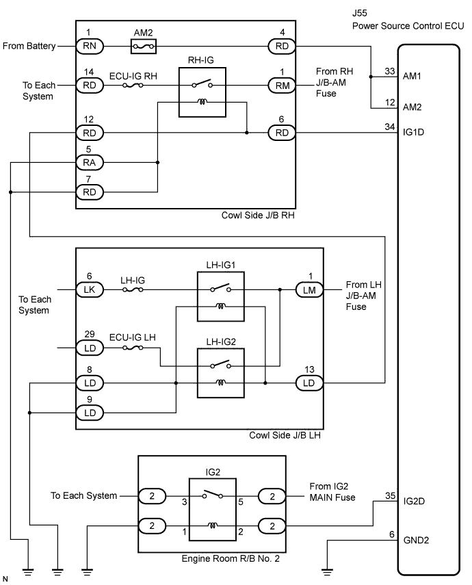
This DTC is output when a problem such as an open in the AM2 fuse, an open or short in the wire harness between the fuse and power source control ECU, a short in the IG output circuit inside the power source control ECU, a short between the power source control ECU and relay, and a short in the relay is detected.
- When the power source control ECU is replaced with a new one and the negative (-) battery terminal is connected, the power source mode becomes the IG-ON mode. When the battery is removed and reinstalled, the power source mode that was selected when the battery was removed is restored.
| DTC No. | DTC Detection Condition | Trouble Area |
| B2271 |
Hold circuit, IG1 relay actuation circuit or IG2 relay actuation circuit inside power source control ECU is open or short |
AM2 fuse
IG2 relay
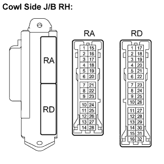
Cowl side J/B RH
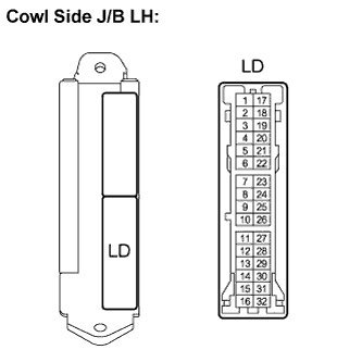
Cowl side J/B LH
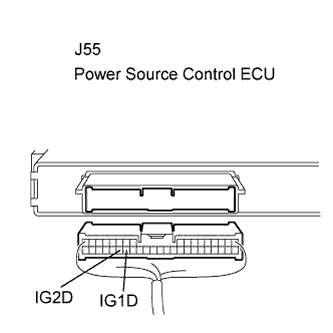
Power source control ECU
Wire harness or connector
|
WIRING DIAGRAM
INSPECTION PROCEDURE
Remove the AM2 fuse from the cowl side J/B RH.
Measure the resistance of the fuse.
- Standard resistance:
- Below 1 Ω
RH-IG relay:
Disconnect the cowl side J/B RH connectors.
Measure the resistance according to the value(s) in the table below.
- Standard resistance:
| Tester Connection | Condition | Specified Condition |
| RD-6 - RA-5 or RD-7 | Always | 136 to 250 Ω at 20°C (68°F) |
| RD-6 - Body ground | Always | 10 kΩ or higher |
LH-IG relay:
Disconnect the cowl side J/B LH connectors.
Measure the resistance according to the value(s) in the table below.
- Standard resistance:
| Tester Connection | Condition | Specified Condition |
| LD-13 - LD-8 or LD-9 | Always | 68 to 250 Ω at 20°C (68°F) |
| LD-13 - Body ground | Always | 10 kΩ or higher |
| 6.CHECK WIRE HARNESS (POWER SOURCE CONTROL ECU - BODY GROUND) |
Measure the resistance according to the value(s) in the table below.
- Standard resistance:
| Tester Connection (Symbols) | Condition | Specified Condition |
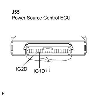
| J55-34 (IG1D) - Body ground | Always | 10 kΩ or higher |
| J55-35 (IG2D) - Body ground | Always | 10 kΩ or higher |
| 7.CHECK WIRE HARNESS (COWL SIDE J/B LH - BODY GROUND) |
Measure the resistance according to the value(s) in the table below.
- Standard resistance:
| Tester Connection | Condition | Specified Condition |
| LD-13 - Body ground | Always | 10 kΩ or higher |
| 8.CHECK WIRE HARNESS (POWER SOURCE CONTROL ECU - BODY GROUND) |
Reconnect the J55 ECU and J/B connectors.
Measure the voltage according to the value(s) in the table below.
- Standard voltage:
| Tester Connection (Symbols) | Condition | Specified Condition |
| J55-34 (IG1D) - Body ground | Engine switch off | Below 1 V |
| Engine switch on (IG) | Output voltage at terminal AM2 is -2 V or more. |
| J55-35 (IG2D) - Body ground | Engine switch off | Below 1 V |
| Engine switch on (IG) | Output voltage at terminal AM2 is -2 V or more. |
| | REPLACE POWER SOURCE CONTROL ECU |
|
|
After DTCs are all cleared, turn the engine switch on (IG). After 30 seconds have elapsed, check for DTCs again.
- OK:
- DTC B2271 is not output.
| | REPLACE POWER SOURCE CONTROL ECU |
|
|
| OK | |
| |
| CHECK INTERMITTENT PROBLEMS |
|
| 10.REPLACE FAULTY RELAY OR J/B AND CHECK POWER SOURCE CONTROL ECU |
Replace a faulty relay or J/B and then connect the power source control ECU connector.
Measure the voltage according to the value(s) in the table below.
- Standard voltage:
| Tester Connection (Symbols) | Condition | Specified Condition |
| J55-34 (IG1D) - Body ground | Engine switch off | Below 1 V |
| Engine switch on (IG) | Output voltage at terminal AM2 is -2 V or more. |
| J55-35 (IG2D) - Body ground | Engine switch off | Below 1 V |
| Engine switch on (IG) | Output voltage at terminal AM2 is -2 V or more. |
| | REPLACE POWER SOURCE CONTROL ECU |
|
|
| 11.REPAIR OR REPLACE WIRE HARNESS OR CONNECTOR AND CHECK POWER SOURCE CONTROL ECU |
Repair or replace a faulty wire harness or connector and then connect the power source control ECU connector.
Measure the voltage according to the value(s) in the table below.
- Standard voltage:
| Tester Connection (Symbols) | Condition | Specified Condition |
| J55-34 (IG1D) - Body ground | Engine switch off | Below 1 V |
| Engine switch on (IG) | Output voltage at terminal AM2 is -2 V or more. |
| J55-35 (IG2D) - Body ground | Engine switch off | Below 1 V |
| Engine switch on (IG) | Output voltage at terminal AM2 is -2 V or more. |
| | REPLACE POWER SOURCE CONTROL ECU |
|
|