Rear Stabilizer Bar Installation
Suspension. Toyota Rav4. Aca30, 33, 38 Gsa33 Zsa30, 35
INSTALL REAR STABILIZER BUSH
INSTALL REAR STABILIZER BAR
INSTALL REAR NO. 1 STABILIZER BAR BRACKET
INSTALL REAR COIL SPRING INSULATOR LOWER LH
INSTALL REAR COIL SPRING LH
INSTALL REAR COIL SPRING INSULATOR UPPER LH
INSTALL REAR COIL SPRING INSULATOR LOWER RH
INSTALL REAR COIL SPRING RH
INSTALL REAR COIL SPRING INSULATOR UPPER RH
TEMPORARILY INSTALL REAR NO. 2 SUSPENSION ARM ASSEMBLY LH
TEMPORARILY INSTALL REAR NO. 2 SUSPENSION ARM ASSEMBLY RH
INSTALL REAR STABILIZER LINK ASSEMBLY LH
INSTALL REAR STABILIZER LINK ASSEMBLY RH
INSTALL SKID CONTROL SENSOR WIRE (for 2WD)
INSTALL REAR SPEED SENSOR LH (for 4WD)
INSTALL REAR SPEED SENSOR RH (for 4WD)
INSTALL REAR WHEEL
STABILIZE SUSPENSION
TIGHTEN REAR NO. 2 SUSPENSION ARM ASSEMBLY LH
TIGHTEN REAR NO. 2 SUSPENSION ARM ASSEMBLY RH
INSPECT AND ADJUST REAR WHEEL ALIGNMENT
CHECK SPEED SENSOR SIGNAL
Rear Stabilizer Bar -- Installation |
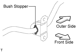
| 1. INSTALL REAR STABILIZER BUSH |
Install the 2 bushes.
- HINT:
- Install each bush to the outer side of the bush stopper on each stabilizer bar.
- Install each bush with its slit facing the vehicle front side.
| 2. INSTALL REAR STABILIZER BAR |
Install the stabilizer bar to the vehicle.
- NOTICE:
- When installing the stabilizer bar, make sure not to damage the sensor wires, brake hoses, etc.
| 3. INSTALL REAR NO. 1 STABILIZER BAR BRACKET |
Install the bracket with the 2 nuts.
- Torque:
- 60 N*m{612 kgf*cm, 44 ft.*lbf}
| 4. INSTALL REAR COIL SPRING INSULATOR LOWER LH |
Install the insulator lower to the suspension No. 2 arm.
| 5. INSTALL REAR COIL SPRING LH |
Install the coil spring to the suspension No. 2 arm.
| 6. INSTALL REAR COIL SPRING INSULATOR UPPER LH |
Align the stopper part of the insulator upper with the coil spring tip, and install the insulator upper.
| 7. INSTALL REAR COIL SPRING INSULATOR LOWER RH |
- HINT:
- Use the same procedures described for the LH side.
| 8. INSTALL REAR COIL SPRING RH |
- HINT:
- Use the same procedures described for the LH side.
| 9. INSTALL REAR COIL SPRING INSULATOR UPPER RH |
- HINT:
- Use the same procedures described for the LH side.
| 10. TEMPORARILY INSTALL REAR NO. 2 SUSPENSION ARM ASSEMBLY LH |
Temporarily install the No. 2 suspension arm to the suspension member with the bolt and nut.
| 11. TEMPORARILY INSTALL REAR NO. 2 SUSPENSION ARM ASSEMBLY RH |
- HINT:
- Use the same procedures described for the LH side.
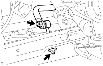
| 12. INSTALL REAR STABILIZER LINK ASSEMBLY LH |
Install the stabilizer link with the 2 nuts.
- Torque:
- for stabilizer bar:
- 74 N*m{755 kgf*cm, 55 ft.*lbf}
- for suspension No. 2 arm:
- 30 N*m{306 kgf*cm, 22 ft.*lbf}
| 13. INSTALL REAR STABILIZER LINK ASSEMBLY RH |
- HINT:
- Use the same procedures described for the LH side.
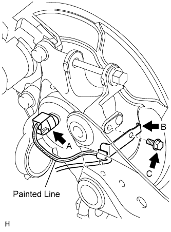
| 14. INSTALL SKID CONTROL SENSOR WIRE (for 2WD) |
- NOTICE:
- To prevent interference with other parts, do not twist the painted line areas of the sensor wire when installing it.
Connect the skid control sensor wire connector (labeled A) to the skid control sensor.
Install the sensor clamp (labeled B) with the bolt (labeled C).
- Torque:
- 8.5 N*m{87 kgf*cm, 75 in.*lbf}
- NOTICE:
- Do not twist the sensor wire when installing the clamp.
Install the sensor clamps (labeled D) with the 2 nuts (labeled E).
- Torque:
- 5.0 N*m{51 kgf*cm, 44 in.*lbf}
- NOTICE:
- Do not twist the sensor wire when installing the clamps.
Install the sensor clamp (labeled F) with the bolt (labeled G).
- Torque:
- 8.5 N*m{87 kgf*cm, 75 in.*lbf}
- NOTICE:
- Do not twist the sensor wire when installing the clamp.
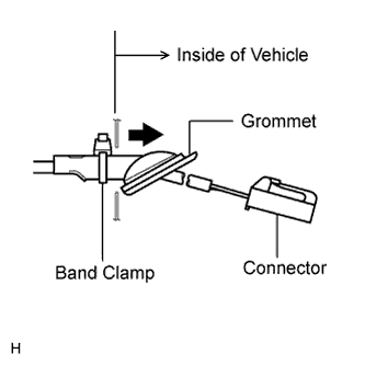
Insert the connector and grommet into the inside of the vehicle through the passage hole in the wheel house.
- NOTICE:
- Make sure the grommet band clamp remains on the outside of the vehicle.
Hold the grommet and pull it toward the outside of the vehicle. Then fix the grommet in place so that it is not tilted.
- NOTICE:
- When pulling out the grommet, do not grip the sensor wire.
- Fix the grommet in place within the range shown in the illustration.
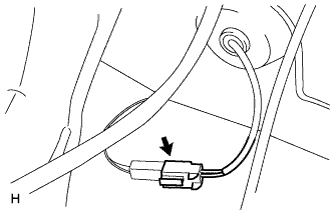
Connect the skid control sensor wire connector.
| 15. INSTALL REAR SPEED SENSOR LH (for 4WD) |
- NOTICE:
- To prevent interference with other parts, do not twist the sensor wire's painted line areas when installing it.
Install the sensor (labeled A) with the bolt (labeled B).
- Torque:
- 8.5 N*m{87 kgf*cm, 75 in.*lbf}
- NOTICE:
- Keep the sensor tip and sensor installation hole free from foreign matter.
- To prevent interference with the bearing rotor, do not rotate the sensor body when inserting the sensor body or after inserting the sensor body.
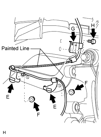
Install the sensor clamp (labeled C) with the nut (labeled D).
- Torque:
- 5.0 N*m{51 kgf*cm, 44 in.*lbf}
Install the sensor clamps (labeled E) with the 2 nuts (labeled F).
- Torque:
- 5.0 N*m{51 kgf*cm, 44 in.*lbf}
- NOTICE:
- Do not twist the sensor wire when installing the clamps.
Install the sensor clamp (labeled G) with the bolt (labeled H).
- Torque:
- 8.5 N*m{87 kgf*cm, 75 in.*lbf}
- NOTICE:
- Do not twist the sensor wire when installing the clamp.
Insert the connector and grommet to the inside of the vehicle through the passage hole in the wheel house.
- NOTICE:
- Make sure the grommet band clamp remains on the outside of the vehicle.
Hold the grommet and pull it from the inside of the vehicle to the outside of the vehicle. Then fix it in place so that it is not tilted.
- NOTICE:
- When pulling out the grommet, do not grip the sensor wire.
- Fix the grommet in place within the range shown in the illustration.
Connect the speed sensor connector.
| 16. INSTALL REAR SPEED SENSOR RH (for 4WD) |
- HINT:
- Use the same procedures described for the LH side.
- Torque:
- 103 N*m{1050 kgf*cm, 76 ft.*lbf}
Lower the vehicle.
Press down on the vehicle several times to stabilize the suspension.
| 19. TIGHTEN REAR NO. 2 SUSPENSION ARM ASSEMBLY LH |
Install the nut and 2 bolts.
- Torque:
- 90 N*m{918 kgf*cm, 66 ft.*lbf}
- NOTICE:
- Do not tighten the nut.
| 20. TIGHTEN REAR NO. 2 SUSPENSION ARM ASSEMBLY RH |
- HINT:
- Use the same procedures described for the LH side.
| 21. INSPECT AND ADJUST REAR WHEEL ALIGNMENT |
Inspect and adjust the rear wheel alignment (RAV4_ACA30 RM00000227X006X.html).
| 22. CHECK SPEED SENSOR SIGNAL |
w/o VSC:
Check the speed sensor signal (RAV4_ACA30 RM000000ONI01MX.html).
w/ VSC:
Check the speed sensor signal (RAV4_ACA30 RM0000022CZ007X.html).