Rear Drive Shaft Assembly -- Installation |
- HINT:
- Use the same procedures for the RH side and LH side.
- The procedures listed below are for the LH side.
| 1. INSTALL REAR DRIVE SHAFT ASSEMBLY LH |
Align the splines of the rear drive shaft outboard joints and, install the left and right rear drive shafts to the axle hub.
| 2. INSTALL DIFFERENTIAL CARRIER ASSEMBLY |
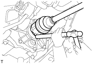
Apply hypoid gear oil to the splines of the left and right rear drive shaft inboard joints.
Align the splines of the rear drive shaft inboard joints and, using a brass bar and hammer, tap in the left and right rear drive shafts.
- NOTICE:
- Face the cutout section of the snap ring downward.
- Do not damage the oil seal during the insertion.
- Do not strike the tip of the outboard joint with the hammer.
- HINT:
- Determine whether or not the rear drive shaft is completely tapped in by checking for changes in sound or the reaction force of the brass bar.
 |
Slowly raise the transmission jack, fix the nuts in place and install the 3 bolts.
- Torque:
- 86 N*m{877 kgf*cm, 63 ft.*lbf} for bolt A
- 140 N*m{1428 kgf*cm, 103 ft.*lbf} for bolt B
- NOTICE:
- Tighten the bolts, not the nuts.
 |
| 3. INSTALL REAR SPEED SENSOR LH |
Install the speed sensor (RAV4_ACA30 RM000001XVJ003X_02_0001.html).
| 4. INSTALL REAR AXLE SHAFT NUT |
Clean the threaded parts on the drive shaft and a new axle shaft nut using a non-residue solvent.
- NOTICE:
- Be sure to perform this work for a new drive shaft.
- Keep the threaded parts free of oil and foreign objects.
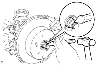
Install a new hub nut.
- Torque:
- 216 N*m{2203 kgf*cm, 159 ft.*lbf}
Using a chisel and hammer, stake the hub nut.
 |
| 5. TEMPORARILY INSTALL PROPELLER WITH CENTER BEARING SHAFT ASSEMBLY |
Align the matchmarks of the transfer and propeller shaft.
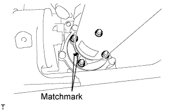 |
Temporarily install the propeller shaft with center bearing with the 4 nuts and 4 washers.
Align the matchmarks of the differential carrier and propeller shaft.
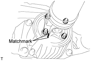 |
Temporarily install the propeller shaft with center bearing with the 4 nuts and 4 washers.
Temporarily install the center support bearing and center support bearing washer with the 2 bolts.
 |
| 6. TIGHTEN PROPELLER WITH CENTER BEARING SHAFT ASSEMBLY |
Tighten the 4 nuts of the propeller shaft and transfer to the torque specification.
- Torque:
- 35 N*m{357 kgf*cm, 26 ft.*lbf}
Tighten the 4 nuts of the propeller shaft and differential carrier to the torque specification.
- Torque:
- 35 N*m{357 kgf*cm, 26 ft.*lbf}
Check that the center line of the center support bearing housing is perpendicular to the axis of the propeller shaft.
Tighten the 2 bolts of the center support bearing to the torque specification.
- Torque:
- 37 N*m{375 kgf*cm, 27 ft.*lbf}
| 7. INSPECT JOINT ANGLE |
- NOTICE:
- Perform the measurement with a 4 post lift or pit so that the vehicle is supported by all 4 wheels as if it were on the ground.
Before the angle measurement, stabilize each part by performing procedures like those described below.
Rotate the propeller shaft several times by hand.
Set the jack to the differential, and raise and lower the differential.
Using SST and a straightedge, measure the angle of the transfer flange (angle D) and the angle of the intermediate shaft (angle A).
- SST
- 09370-50010
- NOTICE:
- Make sure the straightedge and SST are at a right angle.
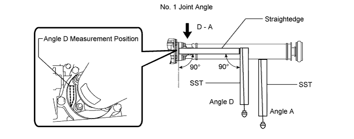
Subtract the measured angle of the intermediate shaft (angle A) from the measured angle of the transfer flange (angle D) to obtain the No. 1 joint angle.
- No. 1 Joint Angle:
Measurement Position No. 1 Joint Angle D - A 2°27' +/-60'
Using SST, measure the angle of the intermediate shaft (angle A) and the angle of the propeller shaft (angle B).
- SST
- 09370-50010
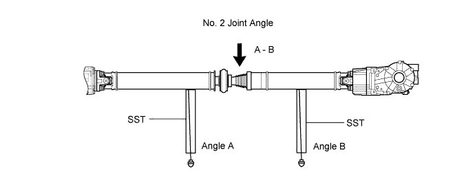
Subtract the measured angle of the propeller shaft (angle B) from the measured angle of the intermediate shaft (angle A) to obtain the No. 2 joint angle.
- No. 2 Joint Angle:
Measurement Position Engine Transmission No. 2 Joint Angle A - B 1AZ-FE A/T 1°29' +/-1°30' M/T 1°28' +/-1°30' 2AZ-FE A/T 1°35' +/-1°30' M/T 1°34' +/-1°30' 2GR-FE A/T 1°35' +/-1°30' 3ZR-FAE M/T 1°28' +/-1°30' CVT 1°29' +/-1°30' 2AD-FTV
2AD-FHVM/T 1°29' +/-1°30'
Using SST, measure the angle of the propeller shaft (angle B) and the angle of the rear differential (angle C).
- SST
- 09370-50010

Subtract the measured angle of the propeller shaft (angle B) from the measured angle of the rear differential (angle C) to obtain the No. 3 joint angle.
- No. 3 Joint Angle:
Measurement Position Engine Transmission No. 3 Joint Angle B - C 1AZ-FE A/T 2°10' +/-60' M/T 2°11' +/-60' 2AZ-FE A/T 2°04' +/-60' M/T 2GR-FE A/T 2°04' +/-60' 3ZR-FAE M/T 2°11' +/-60' CVT 2°11' +/-60' 2AD-FTV
2AD-FHVM/T 2°10' +/-60'
| 8. INSTALL FRONT EXHAUST PIPE ASSEMBLY |
Install the front pipe for 1AZ-FE (RAV4_ACA30 RM000001XBI002X_01_0002.html).
Install the front pipe for 2AZ-FE (RAV4_ACA30 RM000001XBL01JX_01_0001.html).
Install the front pipe for 3ZR-FAE (RAV4_ACA30 RM000001XBL01KX_01_0001.html).
Install the front pipe for 2GR-FE (RAV4_ACA30 RM00000252Q007X_01_0001.html).
| 9. INSTALL EXHAUST CENTER PIPE ASSEMBLY |
Install the center pipe for 1AZ-FE (RAV4_ACA30 RM000001XBI002X_01_0003.html).
Install the center pipe for 2AZ-FE (RAV4_ACA30 RM000001XBL01JX_01_0002.html).
Install the center pipe for 3ZR-FAE (RAV4_ACA30 RM000001XBL01KX_01_0002.html).
Install the center pipe for 2GR-FE (RAV4_ACA30 RM00000252Q007X_01_0010.html).
| 10. INSTALL NO. 2 EXHAUST PIPE SUB-ASSEMBLY |
Install the No. 2 exhaust pipe sub-assembly for 2GR-FE (RAV4_ACA30 RM00000252Q007X_01_0003.html).
| 11. INSTALL TAILPIPE ASSEMBLY |
Install the tailpipe for 1AZ-FE (RAV4_ACA30 RM000001XBI002X_01_0004.html).
Install the tailpipe for 2AZ-FE (RAV4_ACA30 RM000001XBL01JX_01_0003.html).
Install the tailpipe for 3ZR-FAE (RAV4_ACA30 RM000001XBL01KX_01_0003.html).
Install the tailpipe for 2GR-FE (RAV4_ACA30 RM00000252Q007X_01_0004.html).
| 12. INSTALL REAR WHEEL |
- Torque:
- 103 N*m{1050 kgf*cm, 76 ft.*lbf}
| 13. ADD DIFFERENTIAL OIL |
Add differential oil (RAV4_ACA30 RM000002270001X_01_0001.html).
| 14. CONNECT CABLE TO NEGATIVE BATTERY TERMINAL |
| 15. CHECK FOR DIFFERENTIAL OIL LEAKAGE |
| 16. CHECK FOR EXHAUST GAS LEAKAGE |
- If gas is leaking, tighten the areas necessary to stop the leak. Replace damaged parts as necessary.
| 17. INSPECT AND ADJUST REAR WHEEL ALIGNMENT |
Inspect and adjust the rear wheel alignment (RAV4_ACA30 RM00000227X006X.html).